ESAB CUTMASTER 120
Manual 0-5380 OPERATION
4T-1
SECTION 4 TORCH:
OPERATION
4T.01 Torch Parts Selection
Depending on the type of operation to be done deter-
mines the torch parts to be used.
Type of operation:
Drag cutting, standoff cutting or gouging
Torch parts:
Shield Cup, Cutting Tip, Electrode and Starter
Cartridge
NOTE!
Refer to Section 4T.07 and following for ad-
ditional information on torch parts.
Change the torch parts for a different operation as fol-
lows:
WARNING
Disconnect primary power at the source
before assembling or disassembling power
supply, torch parts, or torch and leads as-
semblies.
NOTE!
The shield cup holds the tip and starter
cartridge in place. Position the torch with
the shield cup facing upward to keep these
parts from falling out when the cup is
removed.
1. Unscrew and remove the shield cup assembly
from the torch head.
2. Remove the Electrode by pulling it straight out
of the Torch Head.
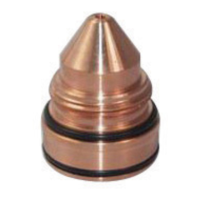
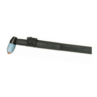
A-03510_AB
Electrode
Start Cartridge
Tip
Shield Cup
Torch Head
Torch Parts (Drag Shield Cap & Shield Cup Body
Shown)
3. Install the replacement Electrode by pushing it
straight into the torch head until it clicks.
4. Install the starter cartridge and desired tip for
the operation into the torch head.
5. Hand tighten the shield cup assembly until it is
seated on the torch head. If resistance is felt
when installing the cup, check the threads before
proceeding.
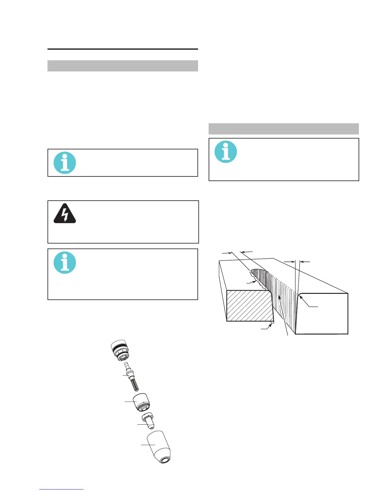
4T.02 Cut Quality
NOTE!
Cut quality depends heavily on setup and
parameters such as torch standoff, align-
ment with the workpiece, cutting speed,
gas pressures, and operator ability.
Cut quality requirements differ depending on applica-
tion. For instance, nitride build - up and bevel angle
may be major factors when the surface will be welded
after cutting. Dross - free cutting is important when fin-
ish cut quality is desired to avoid a secondary cleaning
operation. The following cut quality characteristics are
illustrated in the following figure:
Kerf Width
Cut Surface
Bevel Angle
Top Edge
Rounding
Cut Surface
Drag Lines
Dross
Build-Up
Top
Spatter
A-00007
Cut Quality Characteristics
Cut Surface
The desired or specified condition (smooth or rough)
of the face of the cut.
Nitride Build - Up
Nitride deposits can be left on the surface of the cut
when nitrogen is present in the plasma gas stream.
These buildups may create difficulties if the material
is to be welded after the cutting process.