EasyManua.ls Logo

ESAB Cutmaster 40 - User Manual

ESAB Cutmaster 40
64 pages
Print Icon
To Next Page IconTo Next Page
Loading...
40
120-
240V
esab.com
SAÍDA SAÍDA MÁX.
TENSÃO
Art # A-14396
ALIMENTAÇÃO
DE ENTRADA
FASE
Revision: AC Issue Date: 10 June, 2020 Manual No.: 0-5570
OPERATING
MANUAL
CUTMASTER® 40
PLASMA CUTTING SYSTEM

Table of Contents

Questions and Answers

  • L
    Laura RogersAug 19, 2025
    What to do if FAULT and Communication Fault showing PIP on ESAB Welding System?
    • L
      Leslie HopkinsAug 19, 2025
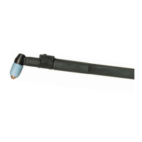
      If the FAULT light is illuminated and the Communication Fault displays PIP on your ESAB Welding System, it could be due to the following reasons: * The shield cup may be loose. Hand-tighten it until it's snug. * The torch might not be properly connected to the power supply. Ensure the torch ATC is securely fastened to the unit. * There may be a problem in the torch and leads PIP circuit. Replace the torch and leads. If these steps don't resolve the issue, the unit may have failed components and require returning it to an authorized service center for repair or replacement.
  • C
    Christopher MorrisonAug 21, 2025
    Why pilot arc is ON but cutting arc will not establish on ESAB Welding System?
    • R
      Randy McdanielAug 21, 2025
      If the pilot arc is on but the cutting arc will not establish on your ESAB Welding System, consider the following: * Ensure the work cable is securely connected to the workpiece. If it is not, connect it. * Check the work cable and connector for any damage. If broken, replace the work cable.
  • R
    rachelbrewerAug 25, 2025
    What to do if GAS LED OFF, Communication Fault showing LoP on ESAB Welding System?
    • D
      Dennis FloresAug 26, 2025
      If the GAS LED is OFF and the Communication Fault shows LoP on your ESAB Welding System, check these items: 1. Make sure the gas supply is connected to the unit. If not, connect it. 2. Verify the gas supply is turned ON. If not, turn it ON. 3. Ensure the gas supply pressure is adequate. Set the air supply inlet pressure to the unit to 120 psi and adjust the leads length to match the actual length being used.
  • G
    galvanjosephAug 27, 2025
    Why torch cutting is diminished on ESAB Welding System?
    • R
      Roberta SmithAug 28, 2025
      If your ESAB Welding System's torch cutting is diminished, consider the following: 1. Check and adjust the current setting to the proper level. 2. Inspect the torch consumables and replace them if they are worn. 3. Ensure a good work cable connection to the workpiece. 4. Reduce the cutting speed if the torch is being moved too fast.
  • D
    Danielle AdamsAug 31, 2025
    What to do if TEMPERATURE LED ON, Communication Fault showing HI on ESAB Welding System?
    • C
      Candice MeyerAug 31, 2025
      If the TEMPERATURE LED is ON and the Communication Fault shows HI on your ESAB Welding System, it could be due to: 1. Obstructed airflow through or around the unit. Refer to the clearance information. 2. Exceeding the unit's duty cycle. Allow the unit to cool down.
  • B
    Brian TorresSep 3, 2025
    What to do if ON / OFF Switch is ON but A/C Indicator does not light on ESAB Welding System?
    • C
      Christina WilliamsSep 3, 2025
      If the ON/OFF switch is ON but the A/C Indicator does not light on your ESAB Welding System, here are some things to check: 1. Ensure the primary power disconnect is in the ON position. If it's off, switch it to ON. 2. Have a qualified person check the primary fuses/breakers to see if they are blown or tripped. 3. Connect the unit to a known good primary power receptacle.
  • J
    jlopezSep 6, 2025
    What to do if nothing happens when torch switch is closed on ESAB Welding System?
    • R
      Robert NelsonSep 6, 2025
      If nothing happens when the torch switch or remote switch is closed (or the CNC START signal is active) and there's no gas flow with the DC LED OFF on your ESAB Welding System, the issue could be: 1. A problem in the torch and leads switch circuit (or remote pendant switch circuit). Take the torch and leads (or remote pendant) to an authorized repair facility. 2. Gas pressure too high. Reduce gas pressure.
  • R
    Ryan AllenSep 9, 2025
    What causes Fault indicator showing Error Code E02 on ESAB Welding System?
    • V
      vasquezashleySep 9, 2025
      If the Fault indicator on your ESAB Welding System is displaying Error Code E02, it could be due to: 1. A primary input voltage problem. Have a qualified person check the primary voltage to ensure it meets the unit requirements.
  • S
    smithtracySep 12, 2025
    What to do if no Fault lights ON, no arc in torch on ESAB Welding System?
    • J
      Jennifer SchroederSep 12, 2025
      If there are no Fault lights ON and no arc in the torch of your ESAB Welding System, it means that you should return it to an authorized service center for repair.
  • J
    Joseph FosterNov 15, 2025
    What to do if FAULT and Communication Fault showing PIC on ESAB Welding System?
    • A
      Amber StevensNov 15, 2025
      If the FAULT light is ON and the Communication Fault shows PIC on your ESAB Welding System, the issue might be due to several reasons: 1. The torch shield cup could be loose. Try tightening it by hand, but be careful not to overtighten. 2. A torch tip, electrode, or starter cartridge might be missing. Turn off the power supply, remove the shield cup, and install any missing parts. 3. The torch start cartridge could be stuck. Turn off the power supply, bleed down the system pressure, remove the shield cup, tip, and start cartridge. Check the start cartridge's lower end fitting for free movement; replace it if it doesn't move freely. 4. The unit's inlet gas pressure might be too high, causing continuous gas flow. Decrease the gas supply pressure to 125 PSI or less. 5. There might be an...

Summary

General Information and Warnings

Notes, Cautions, and Warnings

Explains the categorization of important information using notes, cautions, and warnings.

System Introduction and Specifications

How to Use This Manual

Guide on how to effectively use the manual for safe operation and obtaining copies.

Equipment Identification

Instructions on identifying the unit using model, serial, and part numbers found on data tags.

Receipt of Equipment

Procedures for inspecting equipment upon receipt and reporting any shipping damage.

Power Supply Specifications (CSA)

Details CSA specifications for input power, output current, gas filtering, and inlet pressure.

Input Wiring Specifications (CSA)

Outlines CSA input wiring requirements, circuit protection, and wire sizes for different voltages.

Power Supply Specifications (CE)

Lists CE specifications for input power, output current, gas filtering, and inlet pressure.

Input Wiring Specifications (CE)

Provides CE input wiring requirements, circuit protection, and wire sizes for 230V.

Generator Recommendations

Recommendations for generator ratings to power the CM40 plasma cutting system.

Torch Introduction and Specifications

Scope of Manual

Details the manual's coverage, target audience, and warranty caveats for the SL60™ Plasma Cutting Torch.

Torch Specifications

Lists detailed specifications for torch configurations, parts, ratings, gas requirements, and hazards.

System Installation Procedures

Unpacking the Equipment

Step-by-step instructions for unpacking the equipment and verifying contents.

Lifting and Moving Options

Safety guidelines and procedures for lifting and moving the power supply unit.

Gas Connections

Instructions on how to connect the compressed air supply to the unit's inlet port.

Primary Input Power Connections

Details connecting the unit to the primary power source, including cord types and adapters.

Work Lead Connections

Instructions for connecting the work lead to the power supply and the workpiece.

Torch Installation

Torch Connections

Procedure for connecting the ESAB SL60 or SL60QD™ Torch to the power supply.

System Operation

Front Panel Controls and Features

Identifies and describes the main controls and indicators on the power supply's front panel.

Preparations for Operation

Steps to prepare for operation, including torch selection, connection, power source, and air supply checks.

Torch Operation

Torch Parts Selection

Guide on selecting correct torch parts based on operation type (drag, standoff, gouging).

Hand Torch Operation

Instructions on how to hold and operate the hand torch, including starting the pilot arc.

Plasma Gouging Techniques

Parameters and techniques for plasma gouging, including lead angle, standoff, and slag management.

Patent Information

Lists patents covering various plasma cutting torch parts and pending patents.

System Service and Maintenance

General Maintenance Schedule

Routine maintenance tasks and schedule for the power supply unit.

Common Faults and Causes

Lists common operational problems, their causes, and recommended troubleshooting actions.

Fault Indicator Codes

Explains fault codes displayed on the unit and their meanings for troubleshooting.

Basic Troubleshooting Guide

A guide to identify and resolve common issues with the plasma cutting system.

Power Supply Parts Replacement

Procedures for replacing the optional single-stage filter element in the power supply.

Torch Service and Maintenance

General Torch Maintenance

Guidelines for cleaning and lubricating the torch for optimal performance and longevity.

Consumable Torch Parts

Instructions for inspecting and replacing consumable parts of the plasma torch.

Parts Lists and Ordering

Parts List Introduction

Overview of the parts list breakdown, ordering information, and return policy.

Ordering Information

Guidance on how to order replacement parts, including required information.

Power Supply Replacement Parts

Lists items included with a replacement power supply unit.

Replacement Power Supply Parts

Catalog numbers for replacement parts for the power supply unit.

Options and Accessories

Catalog numbers for optional accessories and replacement parts.

External Replacement Parts

Identifies external replacement parts for the unit with corresponding catalog numbers.

Hand Torch Replacement Parts

Catalog numbers and diagrams for replacement parts specific to the hand torch.

SL60 QD Hand Torch Parts

Catalog numbers and diagrams for replacement parts for the SL60QD hand torch.

Torch Consumable Parts (SL60)

Identifies consumable parts for the SL60 torch with associated part numbers and diagrams.

Appendix 1: Data Tag Information

Data Tag Details and Symbols

Explains the information found on the unit's data tag, including symbols and voltage/current ratings.

Appendix 2: Torch Pin-Out Diagrams

Hand Torch Pin-Out Diagram

Illustrates the pin configurations for the ATC male connector and female receptacle on the hand torch.

Appendix 3: Torch Connection Diagrams

Hand Torch Connection Diagram

Shows the wiring schematic for connecting the hand torch leads to the power supply.

ESAB Cutmaster 40 Specifications

General IconGeneral
BrandESAB
ModelCutmaster 40
CategoryCutter
LanguageEnglish

Related product manuals