CUTMASTER 40
0-5570 TORCH OPERATION
35
4T.03 Gouging
WARNING
Be sure the operator is equipped with proper
gloves, clothing, eye and ear protection and that
all safety precautions at the front of this manual
have been followed. Make sure no part of the op-
erator’s body comes in contact with the workpiece
when the torch is activated.
Disconnect primary power to the system before
disassembling the torch, leads, or power supply.
CAUTION
Sparks from plasma gouging can cause damage
to coated, painted or other surfaces such as glass,
plastic, and metal.
Check torch parts. The torch parts must
correspond with the type of operation. Refer to
Section 4T.07, Torch Parts Selection.
Gouging Parameters
Gouging performance depends on parame-
ters such as torch travel speed, current level,
lead angle (the angle between the torch and
workpiece), and the distance between the
torch tip and workpiece (stando).
CAUTION
Touching the torch tip or shield cup to the work
surface will cause excessive parts wear.
Torch Travel Speed
NOTE!
Refer to Appendix Pages for additional informa-
tion as related to the Power Supply used.
Optimum torch travel speed is dependent
on current setting, lead angle, and mode of
operation (hand or machine torch).
Current Setting
Current settings depend on torch travel
speed, mode of operation (hand or machine
torch), and the amount of material to be
removed.
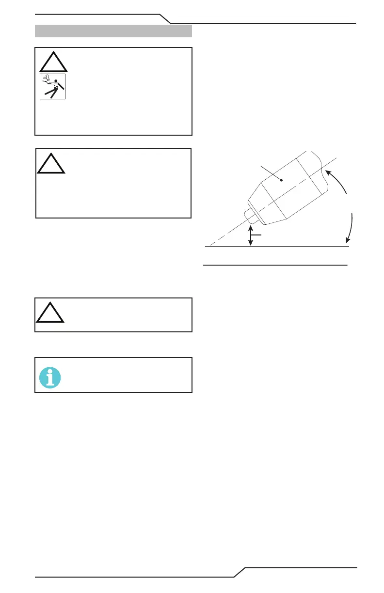
Lead Angle
The angle between the torch and workpiece
depends on the output current setting and
torch travel speed. The recommended lead
angle is 35°. At a lead angle greater than 45°
the molten metal will not be blown out of
the gouge and may be blown back onto the
torch. If the lead angle is too small (less than
35°), less material may be removed, requiring
more passes. In some applications, such as
removing welds or working with light metal,
this may be desirable.
35°
Workpiece
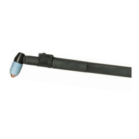
Torch Head
Standoff Height
A-00941_AB
Gouging Angle and Stando Distance
Stando Distance
The tip to work distance aects gouge qual-
ity and depth. Stando distance of 1/8 - 1/4
inch (3 - 6 mm) allows for smooth, consistent
metal removal. Smaller stando distances
may result in a severance cut rather than a
gouge. Stando distances greater than 1/4
inch (6 mm) may result in minimal metal
removal or loss of transferred main arc.
Slag Buildup
Slag generated by gouging on materials such
as carbon and stainless steels, nickels, and
alloyed steels, can be removed easily in most
cases. Slag does not obstruct the gouging
process if it accumulates to the side of the
gouge path. However, slag build - up can
cause inconsistencies and irregular metal
removal if large amounts of material build
up in front of the arc. The build - up is most
often a result of improper travel speed, lead
angle, or stando height.