30
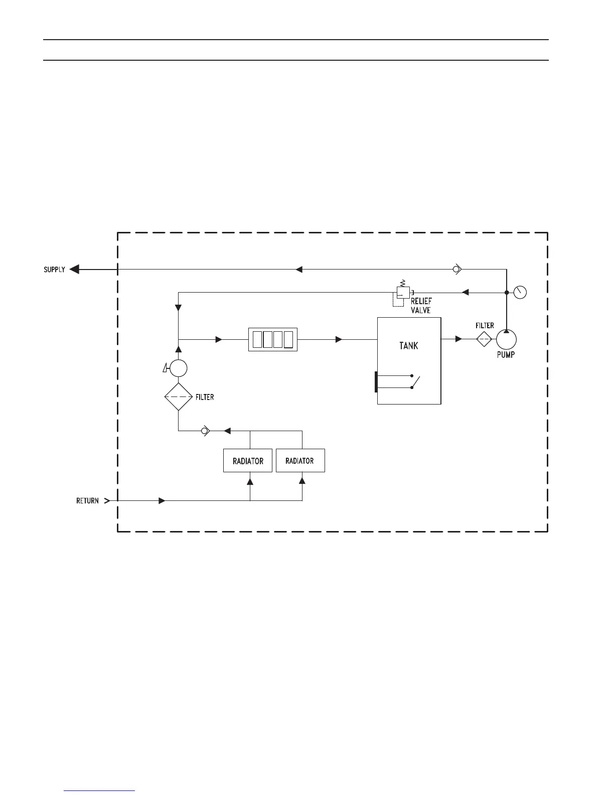
As soon as the power source is supplied with input power, the coolant pump motor turns ON. Coolant pumps
out to the torch and returns back to the coolant tank through the radiators, lter, ow sensor, and IGBTs cold
plate respectively. The pump has an internal adjustable bypass valve set to 250 psi (17 bar). There is also an ex-
ternal adjustable regulator, set to 175 psi (12 bar), to bypass the coolant ow if pressure exceeds 175 psi (12 bar).
The coolant ow diagram is as shown in the gure below.
4.1.1 EPP-362 Coolant Flow Diagram
SECTION 4 OPERATION
FLOW SENSOR (FS1)
IGBT COLD PLATE
LEVEL SENSOR
(LS1)
GAUGE
Coolant Flow Diagram