42
SECTION 6 TROUBLESHOOTING
6.2 Help Codes
When fault light is in either one of the above-mentioned states, check the CNC/Process Controller screen for the
complete description of the error.
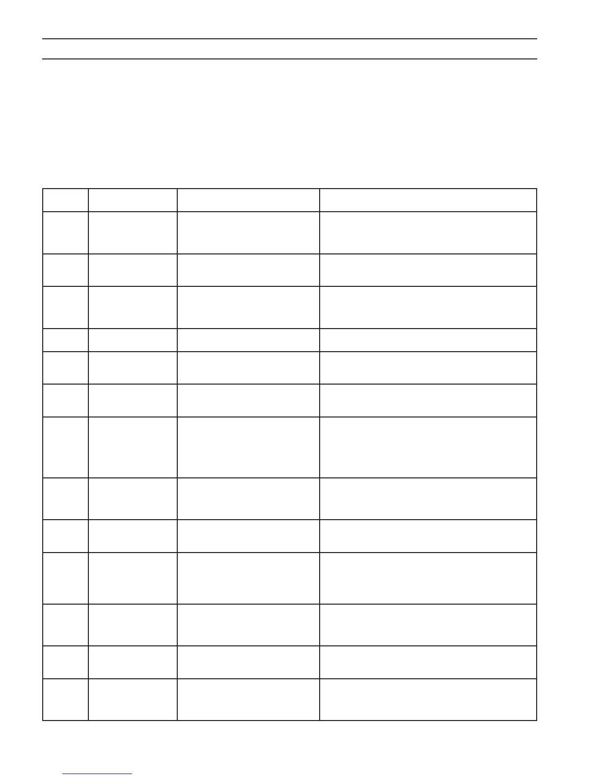
The list of errors with detail description for EPP 202 are shown in the table below
Error code
displayed
Error Name Description Explanation
1 LINE VOLT, IDLE Supply Line Voltage exceeded or
dropped below + or - 15% of rated input
when machine is in Idle mode
In idle state, control board’s main micro monitors the bus
voltage. If the bus voltage doesn’t satisfy the threshold limits,
it might be due to abnormal line voltages. Check input line volt-
ages with meter.
2 LINE VOLT,
CUTTING
Supply Line Voltage exceeded or
dropped below + or - 20% of rated input
while cutting
During cutting bus voltage failed to satisfy the threshold limits,
check the input line voltages with meter.
3 CONTROL BIAS Control Transformer not supplying
proper voltage to control board or the
+24 and +/-15 volt bias supplies are not
balanced
Bias supply voltages failed to satisfy the threshold limits. Check
the control transformer voltages on TB3 if they record as per
documentation then replace the control board.
4 THERMAL SWITCH OPEN Thermal switch circuit is open Either diode bridge or IGBT module is overheated. Please check
the coolant ow and main fan operation.
5 START ON POWER UP START signal from the CNC is available
before the power source is powered.
There was a start signal issued from the CNC/Process control-
ler during the start-up of power source. Please check the start
signal and CAN connection.
6 FAIL TO FIRE Failed to re/ ignition did not take place
during the allowed time for arc ignition.
After start signal is issued from the CNC/Process Controller,
power source failed to re. Check the HF relay, consumables, PA
IGBT, and height of torch from the plate.
8 TORCH ERROR Torch error/Electrode current was pres-
ent before the PWM was enabled.
If there is electrode current present before the start signal is
issued or PWM engage signal issued, there might be a short in
the torch cable or electrode and nozzle are touching each other.
Check the torch cable, consumables, and also check the jumper
on J1(RAS) L and J pins inside the RAS box which will simulate
regular and blow-back torch.
9 ARC VOLT. OVER 40V,
IDLE
Arc voltage is greater than 40V in Idle
mode.
There is an output voltage present in the idle state before start
signal issued. This could be due to shorted IGBTs or bad driver
board. Check the IGBTs, gate pulse connections on the driver
board.
11 OVER CURRENT, IDLE Idle mode current is greater than the
minimum idle current.
Current above the threshold limits detected in the idle state.
Check the hall sensors and their connections to the control
board.
12 SINGLE PHASE OPERA-
TION
One phase of power is missing from the
input
Missing phase detected after start command issued (Cutting or
Marking). After power-up, average bus voltage recorded in the
Idle state and in the Cut state. If the dierence between the two
recorded values is greater than 60V, this error is activated. Check
the input fuses and line voltages with meter.
13 OCV FAILURE Open circuit voltage did not reach 280
volts within 200 msec.
During arc ignition, the output voltage recorded failed to
satisfy the threshold limit with in specied time. Check the
consumables, distance between torch and plate. If this error
activates every time please contact ESAB’s service department.
14 AMBIENT TEMP Ambient temperature exceeded 75° C in
control enclosure.
The thermister on the Control Board (PCB1) has detected tem-
peratures over 75° C. Check for overheated components inside
the control cabinet
15 BUS CHARGER FAULT Bus voltage did not reach 200 volts dur-
ing the allowed time.
Bus voltage failed to reach the threshold limit with in specied
time. Check for faulty input fuse, shorted bus lter capacitor, bus
charger contactor (K2) contacts failure, and bus-charger contac-
tor relay (RB1-1) failure.