26
SECTION 3 INSTALLATION
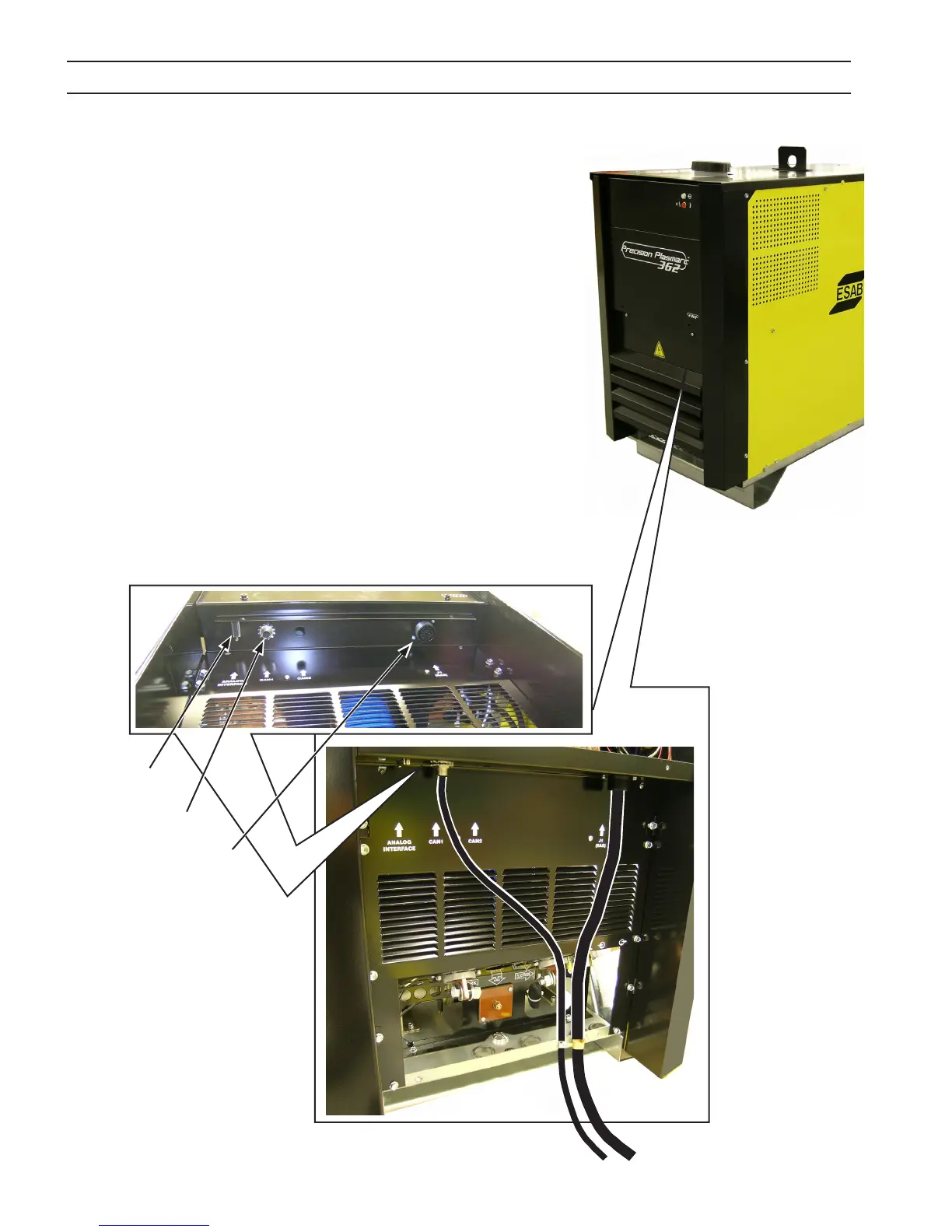
3.8 Interface Cable Connectors
Interface Cable Connectors Panel (bottom side of front panel)
CAN Connector
This is the CAN communication bus connector. The cable from this
connector is tied to the CNC/process controller.
J1 (RAS)
This is a connector for interfacing with Remote Arc Starter (RAS)
unit. The cable from this connector carries signals such as: Mark
Mode and Hi-Frequency ON.
J1 (RAS)
CAN
Analog
Interface
Analog Interface Connector
This connector is used when the plasma unit is used in analog com-
munication mode where the CAN communication is not available.
A junction box is used to connect customer CNC/process controller
to the plasma unit. A shielded DB25-DB25 cable, as mentioned in
section 3.8.3, connects the analog interface connector to the junc-
tion box.