22
SECTION 3 INSTALLATION
Do not connect hoses to a solenoid valve that can be closed when the
pump is operating as damage to pump can result.
3.5 Coolant Connection Procedure
After lling the reservoir, turn ON power source and allow the pump to run with reservoir cap removed in order
to purge air from the radiator, hoses, and torch. Re-check coolant level to ensure reservoir is lled. Replace res-
ervoir cap after purging and checking coolant level. Check for leaks.
CAUTION
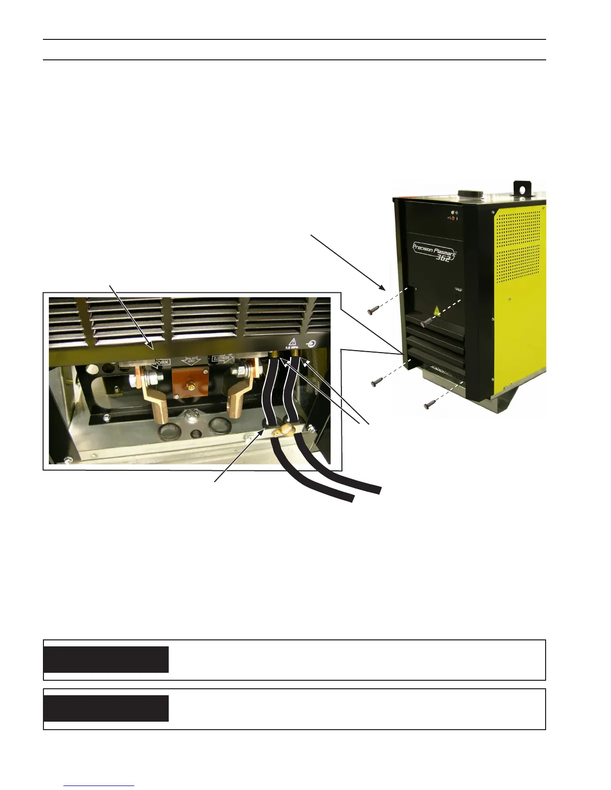
Coolant Connections
Front Access
Panel Opened
1. Open access panel on the lower front of the power source by removing four M6 screws.
2. Thread coolant hoses through the openings at the bottom of the power source immediately behind the
front panel.
3. Connect hoses to designated terminals mounted inside the power source.
4. Close front access panel.
Front Access
Panel Closed
Remove four M6
screws to open
Access Panel
To ease connections, thread cables/
hoses through these 2 access holes
With the torch connected, ll the reservoir with the specially formulated torch coolant (approx 4 gallons). Do not
use regular anti-freeze solutions, such as for an automobile, as the additives will harm the pump and torch. ESAB
P/N 0558004297 is recommended for service down to 12° F (-11° C). ESAB P/N 156F05 is recommended for service
below 12° F (-11° C) to -34° F (-36° C).
Do not allow pump to operate with coolant reservoir empty as per-
manent damage to the pump can result.
CAUTION