38
Operation: The rotor reacts to turbulence, pulsation, entrained air, and other ow anomalies induced in the ow
stream by other process hardware. For optimum performance, install RotorFlow units where nominal ow condi-
tions exist, with ports located at the top. Incoming ow may be placed to either port. A minimum of 8° of straight
pipe on the inlet side is recommended. Frequency output (RFO) is determined by the velocity of the monitored
uid acting on the sensor rotor. Input piping with an orice smaller than that of the sensor input will eect the
sensor output.
Installation: RotorFlow sensors connect to piping via NPT mating thread forms. The following guidelines are
provided to assist with installation for a leak-free seal, without damage to the unit:
1. Apply pipe thread sealant to male pipe threads.
2. Thread RotorFlow unit onto male pipe thread until hand-tight.
3. Tighten pipe 1 to 1-1/2 additional turns.
4. If improper seal results, continue turning pipe into unit in ¼ turn increments.
Recommended Pipe Sealants: (a) Permatex “No More Leaks” (b) Teon Thread Tape.
Filteration and Cleaning: 150 micron lteration is recommended. However, should foreign particles enter the Ro-
torFlow sensor, accumulation is easily cleared by removing the lens from the body. The lens is removed by turn-
ing its center rib 45° counter-clockwise and then pulling it out. To reinstall the lens, simply reverse the process.
Pressure must be relieved from the system prior to sensor clean-out.
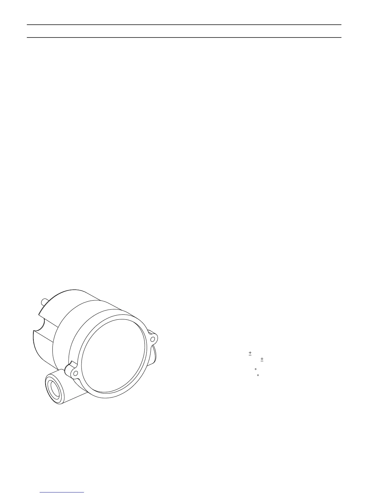
5.3 Flow sensor
RotorFlow Sensor is used to monitor the ow rate of the coolant.
SECTION 5 MAINTENANCE