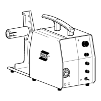
-- 4 --
cmek0de1
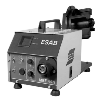
COMPONENT DESCRIPTION
This component description refers to the wiring diagram.
AP01 Main circuit board with control electronics: see the description on
page 7.
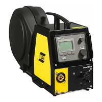
AP02 Circuit board with display: see the description on page 22.
C01 Capacitor 0. 1µF, decoupling.
CXX Capacitor 4700µF. Must be fitted when an intermediate wire feed unit is
in use in extreme applications (low mains voltage and long cables).
G01 Tachogenerator: 660 Hz output at a wire speed of 25 m/min. The
tachogenerator is incorporated in motor M01.
M01 Motor, rated voltage 42 V.
RP01 Potentiometer, 10 kΩ, for setting the wire feed speed.
RP02 Potentiometer, 10 kΩ, f or setting the welding voltage.
RP03 Potentiometer, 10 kΩ, for setting the burn--back time.
RP04 Potentiometer, 10 kΩ, for setting the crater fill time.
SA01 Switch, 2/4--stroke changeover. When the switch is closed, 4--stroke
control mode is selected.
SA02 Switch, Crater fill function On/Off. When the switch is closed, crater fill
function is operative.
XP01 23--pole connector, for connection to the welding power unit.
XP02 Terminal for welding current connection from the power unit.
XS . . Connectors marked XS are socket connectors.
XS02 If circuit board AP01 has part no. 0486 205 880 or 0486 205 882:
the Creep Start function is operative when the connector links B01--B02.
If circuit board AP01 has part no. 0486 205 886 or 0487 166 880:
the Creep Start function is operative when the connector links B02--B03.
XS12 Not mounted, from machine number 514--615--xxxx
XS13 12--pole connector:
MEK 4 with serial number 431--xxx--xxxx
23--pole connector:
MEK 4 from serial number 514--xxx--xxxx and above.
YV01 Solenoid valve