2.1.2. Software Preparation
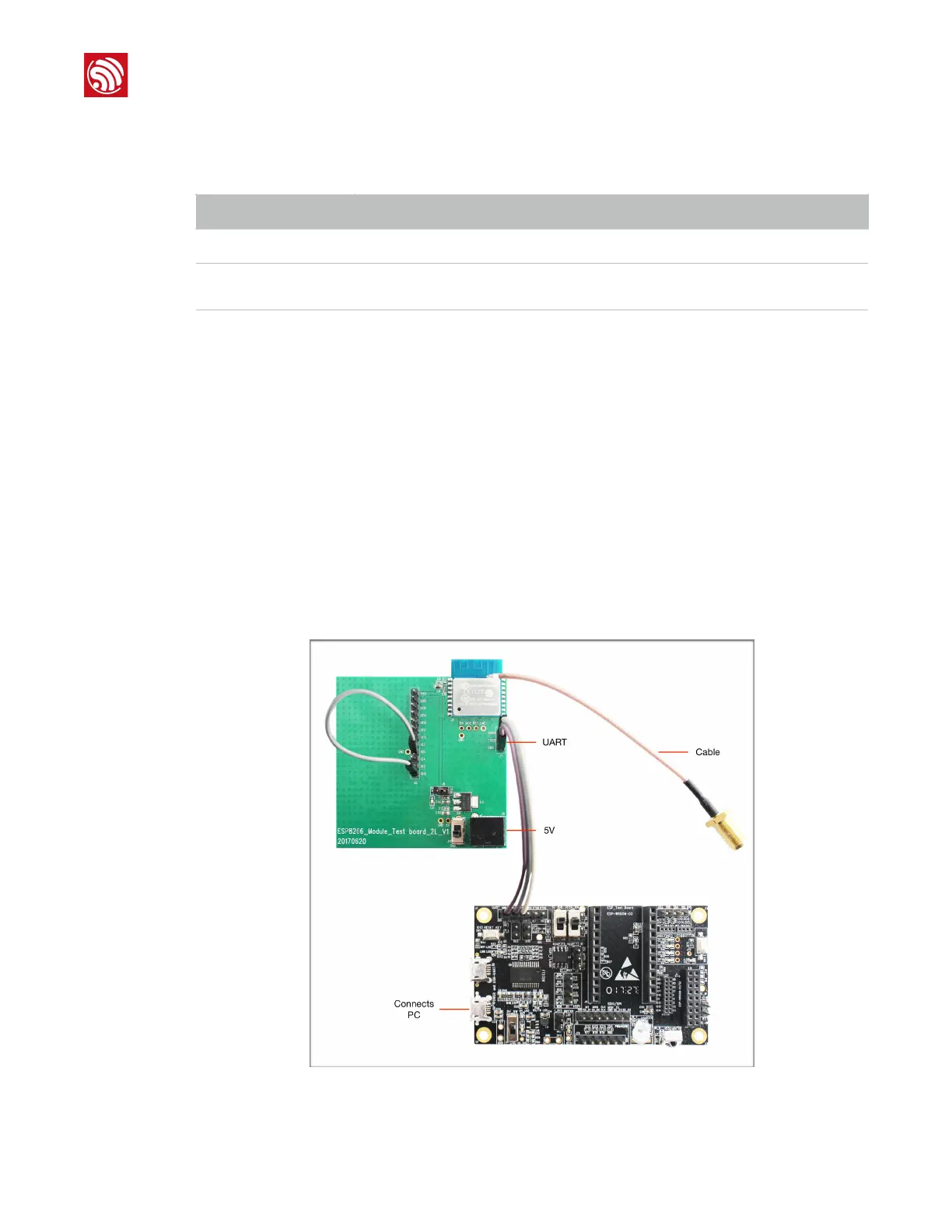
2.2. Hardware Connection
•
Connect the SMA (SubMiniature version A) RF head to the antenna of the DUT. Users
should cut off the PCB antenna of the DUT after soldering the RF cable to it; otherwise,
the test results will be inaccurate.
•
Connect the demo board and the PC via a micro-USB cable. For instructions on how to
install the UART driver on the PC, please refer to Appendix Ⅰ.
• Use Dupont lines to connect the backplane's GND, TXD and RXD pins to the demo
board's GND, TXD and RXD pins, respectively.
The hardware connection for ESP-WROOM-02 is shown in Figure 2-1. To enable its
downloading mode, connect ESP-WROOM-02's GPIO0 and GPIO15 to GND. After
downloading, leave GPIO0 floating and restart the module to enable its working mode.
!
Figure 2-1. Hardware Connection for ESP-WROOM-02