2.4. ESP-Launcher
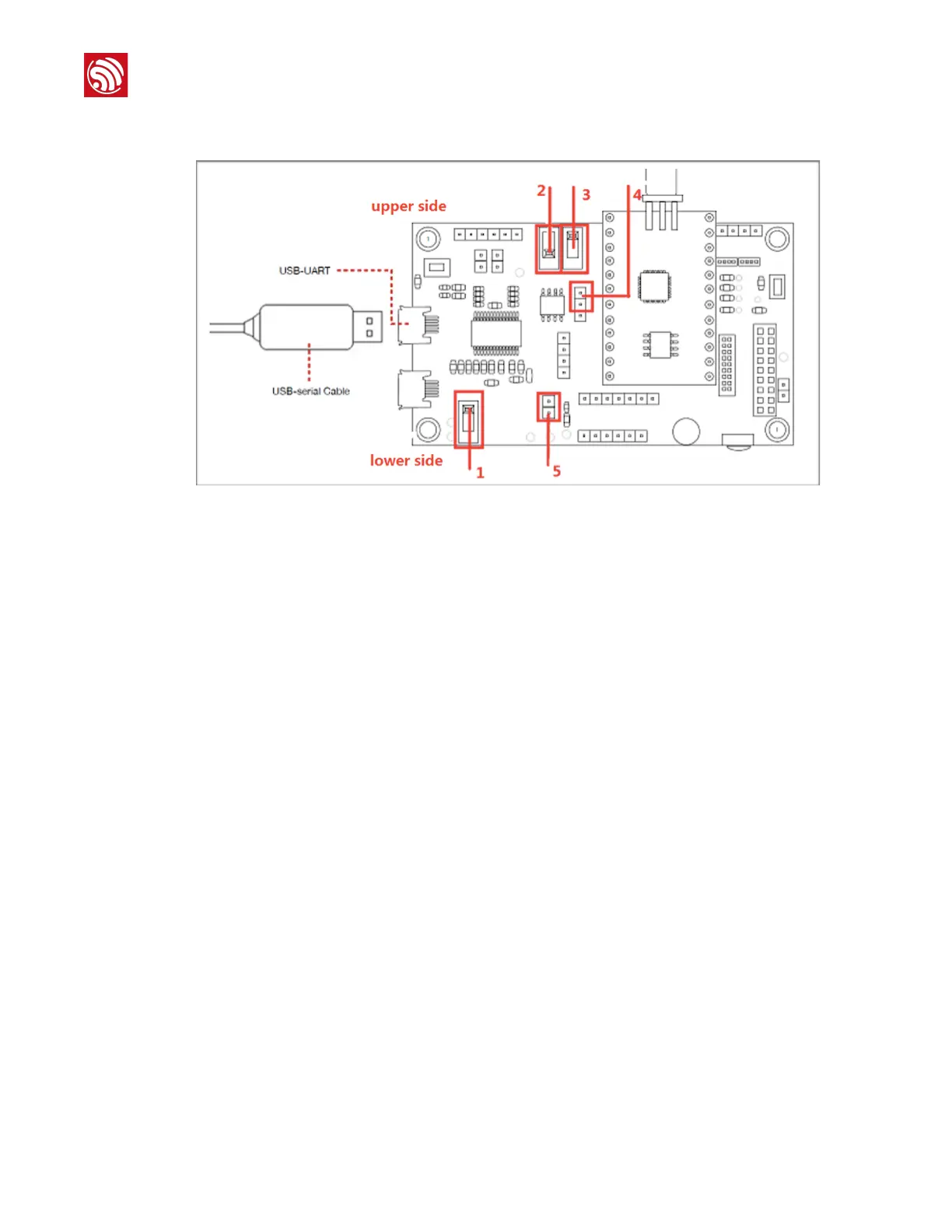
Figure 2-3. ESP-Launcher
• Switch "1": toggle it to the lower side
- Lower side: power-off
- Upper side: power-on
• Switch "2": toggle it to the lower side
- Lower side: firmware download mode
- Upper side: program execution mode
Switch "2" is used to test ESP-Launcher. RF testing on ESP-WROOM-32 and ESP-
WROOM-02 do not require switch "2".
• Switch "3": toggle it to the upper side
This is the chip selection switch that should be toggled to the upper side by default.
•
Pin "4": put a jumper cap on the upper two pins
• Pin "5": put a jumper cap on it
• The VDD33 and GND on ESP-Launcher can be used as the power supply for the DUT.