M
Buffer pump
Room 2
Mixing valve 2
Pump 2
T flow 2
MC2
M
Mixing valve 1
Pump 1
T flow 1
M
MC1
Room 1
Return temp.
Heating
temp.
limiter
Return riser
T
Cold water
A
B
AB
3-way valve
AB
B
A
3-way mixing valve
Start relief
2x0,5²
T outside
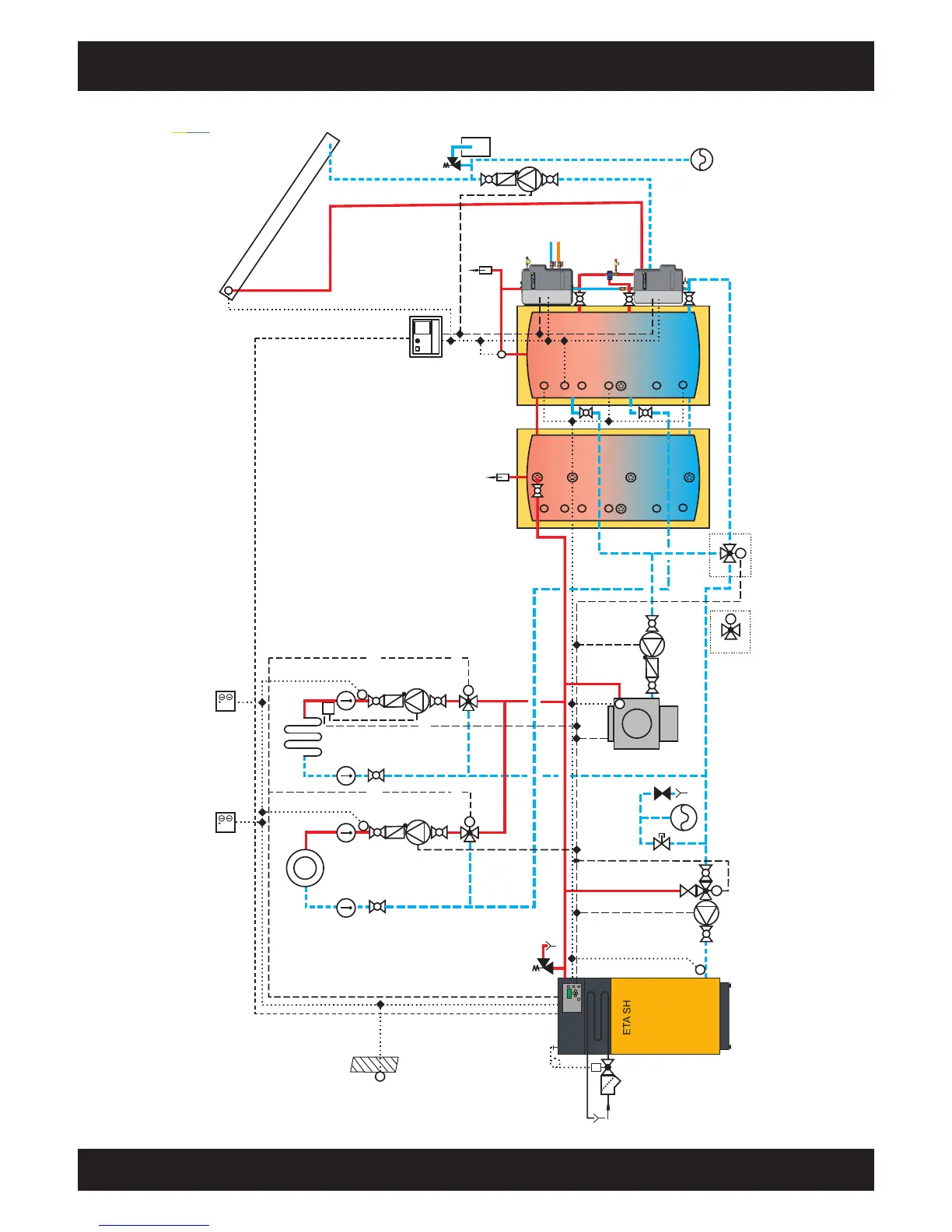
ETA stratified
charging module
2x0,5²
T Collector
2x0,5²
Wall housing for ETA FWM + SLM
for standard control system
Oil/gas boiler
Auxiliary boiler pump
Tres
2x0,5²
3x1²
3x1²
CW
HW
M
DN32
DN32
ETA stratified buffer SP ETA stratified buffer SP
M
2x0,5²
T buffer bottom
T buffer middle
T buffer top
2x0,5²
2x0,5²
Solar buffer bottom²
2x0,5²
Solar buffer top
2x0,5²
T buffer top HW
ETA fresh
water module
4x1²
4x1²
4x1²
3x1²
2x0,5²
3x1²
3x1²
2x0,5²
2x0,5²
4x0,5² 4x0,5²
4x1²
Twisted Pair 2x2x0,6²
CAN bus (L = max. 400m)
Set the enabling temperature for
the heating circuits high enough so
that enough heat remains in buffer
for the fresh water module.
3x1²