ES441.1 - User’s Guide22
Hardware Description ETAS
4.3 Measurement Channels
All measurement channels of the ES441.1 are identical. They consist of an input
stage with signal acquisition and signal processing.
The measurement channels are designed for input voltages of -50 V to +50 V.
The minimum pulse width is limited to 120 ns. This limitation avoids the acquisi-
tion of interfering pulses on the measurement channels. The input impedance is
greater than 2 M.
4.3.1 Input Stage with Signal Acquisition and Signal Processing
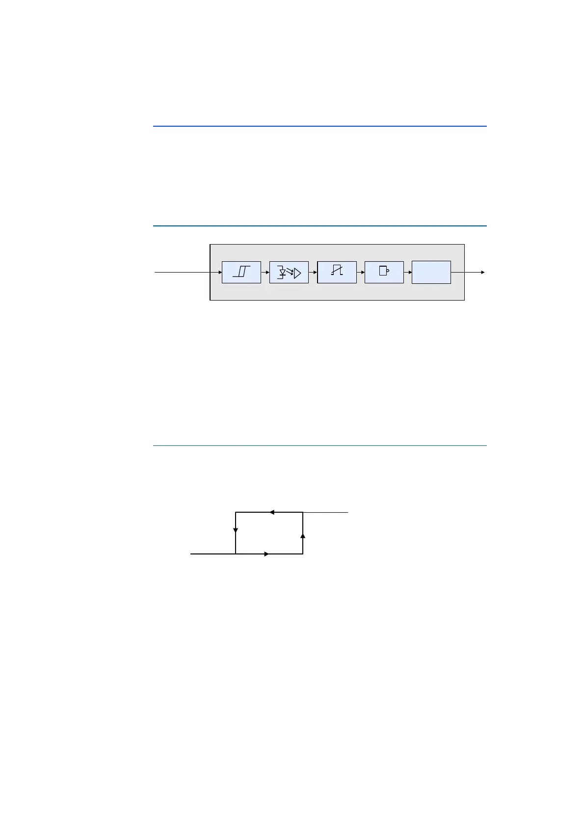
Fig. 4-3 Input Stage
The input stage of every measurement channel (see Fig. 4-3 on page 22) consists
of the following components:
• Schmitt trigger with a configurable hysteresis,
• galvanic isolation,
• interfering voltage filter,
• inverter and
• signal acquisition and signal processing.
Configurable Hysteresis
The hysteresis and the corresponding values for the LOW and HIGH levels can be
configured independently of one another in the calibration software (see Fig. 4-4
on page 22).
Fig. 4-4 Definition of the Hysteresis for the Input Channel
They can be configured separately in a range of -50 V to +50 V for every input
channel of the ES441.1. The minimum resolution of the switching thresholds is
0.1 V. The hysteresis is defined completely by both levels and the edge direction.
The configurable hysteresis results in noise suppression. This feature facilitates
application in environments with noise interference and/or noise signals. The
quality of signal interpretation is improved considerably.
Capturing
Module
-50 V ... +50 V
Invert erGlitch-FilterHysteresis
äçÖáëÅÜ=M
äçÖáëÅÜ=N
efde
mÉÖÉä
ilt
mÉÖÉä


 To Next Page