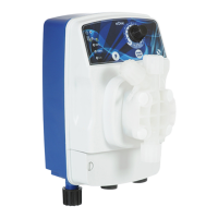
Typical installation
Fig. 6 – Typical installation
Avoid unnecessary curves and narrow on both the discharge and suction pipes. Apply a 3/8 " or ½" BSP female nipple
on the conduct of the plant to be treated, in the most suitable location for the injection of the product to be dosed. This nipple
is not supplied. Screw the injection valve on the nipple using PTFE tape as a seal (Figure 8). Connect the tube to the conical
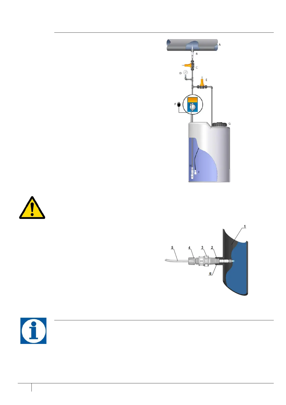
adapter of the injection valve and secure with the hose ring nut (4). The injection valve is also a no-return valve.
1. Plant being treated
2. conical connection 3/8” – ½” BSP
3. injection valve
4. hose ring nut
5. discharge pump hose
6. PTFE sealing type
Fig. 7 - Injection valve mounting
Accessories
Supplied with the pump are includes the following articles:
• n.1 flexible transparent PVC cristal suction hose, length 4m
• n.1 polyethylene semi-rigid white discharge hose, length 2m
• n. 1 3/8” BSP injection valve
• n.1 foot filter
• n.1 instruction manual
 Loading...