12
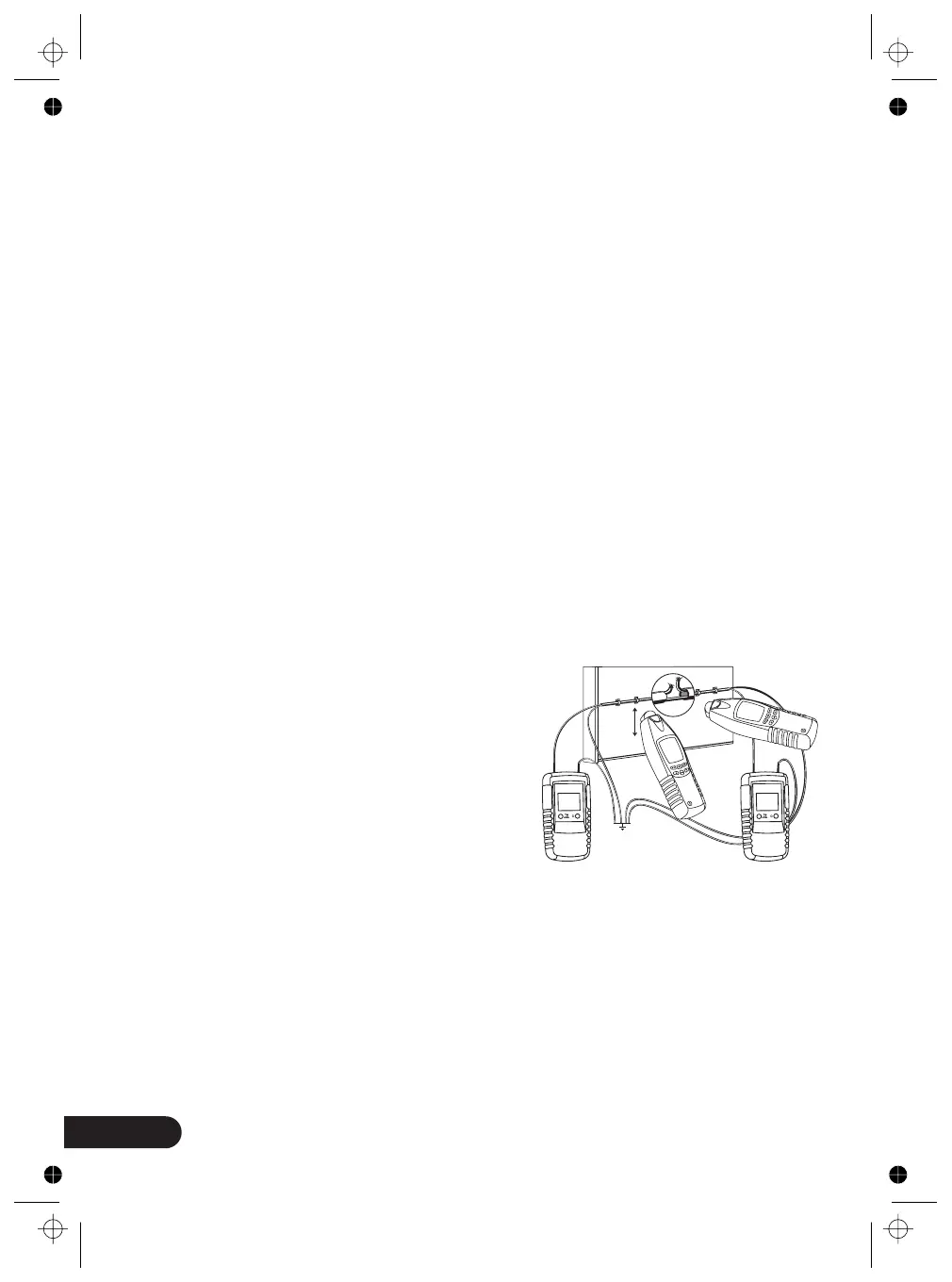
3.6 Locating of line interruptions using two transmitters
(one-pole application)
Requirements:
Note:
When locating a line interruption using one transmitter to feed from one conductor
end, the location of interruptions may not be precisely located in case of bad
conditions due to a field disturbance. The drawbacks described above can easily
be avoided when using two transmitters (one from each end) for line interruption
detection. In this instance, each of the transmitters are set to a different line code
(e.g. transmitter one to code 1 , the other transmitter to code “2“). A second
transmitter with a different line code is not included within the scope of supply
and, therefore, has to be ordered separately.
If the transmitters are connected in accordance with the figure 12, the receiver
indicates 3 at the left side of the line interruption. If you continue further than
the interruption, towards the right, the receiver displays 7 . If you are directly
above the interruption, no line code is displayed, due to the overlapping of both
transmitter signals. The line interruption is located exactly in the middle between
the displayed line codes 3 and 7
• The current circuit must not be live.
• All lines not being used must be connected to the auxiliary ground as shown in
the figure.
• Connect both transmitters as shown in the figure.
• Proceed as described in the application example.
The ground connected to the transmitter and
to the wires not being used can be as follows
is: an auxiliary ground, an orderly connected
ground contact of a home office socket, or an
orderly a grounded water pipe.
Please make sure during line interruption
locating in multi-wire shielded conductors
and cables, that all remaining wires are orderly
grounded. This is required to avoid inductive
disturbance (by capacity coupling).
The locating depth for shielded conductors and cables varies, as the individual
wires within the shield are twisted. The transition resistance of a line interruption
must be higher than 100 kOHM. The verification of resistance can be carried out
by any multimeter.
The switching with button 4 from “LEVEL I” to “LEVEL III” the sensitvity of Distance
is increased up to factor 5.
Setup: manual mode, minimal sensitivity. Tracing depth max. 2 meters.
““
““
““
““ ““.
figure 6
1
2
1
2