EVAstream Electrical connections - PCB Settings EVAstream Electrical connections - PCB Settingswww.evaoptic.com8 9
4 Electrical installation
Electrical shock hazard. Fatal injury will occur. Switch off all electricity near the pool before
performing the electrical installation.
6
DANGER
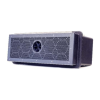
Connect the cables from the EVAstream Turbine to the Motor Control Unit:
l Make sure the cables are properly finished (as shown in the photo). Dismantling length
should be 16 mm.
l Place the red, yellow and blue cable (do not change the colors of the cables) in the
terminal block (like the yellow and blue cables in the drawing).
l Secure the cables by closing the orange clamps in the terminal block (with the T-LOX
knee lever connection) with a standard screwdriver (like the red cable in the drawing).
If the cables are not long enough, they can be extended:
You can extend the cable from the Turbine to the Motor Control Unit with max. 20 m. Use the
EVA CCB 16x25 connection box with a 25 mm
2
or 35 mm
2
cable.
Go to the next step for installation with an extension for the turbine cables or go directly to step
4.2 if extending the cables is not necessary.
L PEN
4.1 Connect EVAstream turbine to Motor Control Unit
Dismantling cable
Length 16 mm
Cable connections in Motor Control Unit
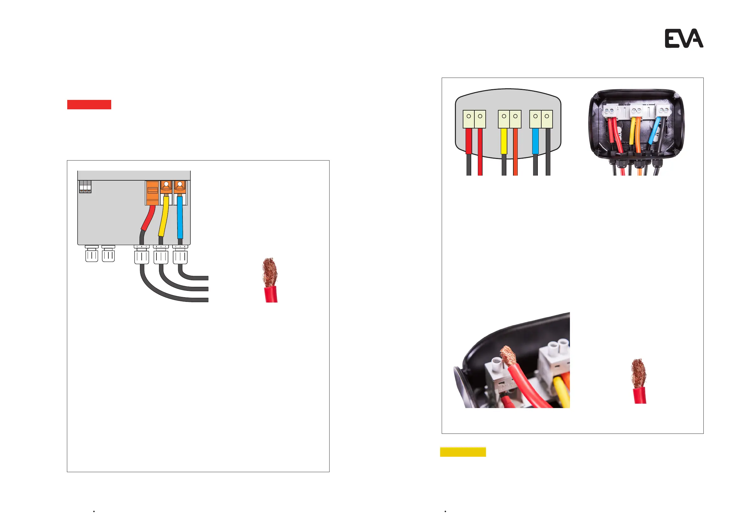
Connect the EVAstream turbine cables to the Connection box (EVA-CCB-16x25)
l Connect the cables (3x1x25mm2 cable) attached to the EVAstream turbine to the
connection box.
l The cable connection box must be placed above the ground, in an accessible place.
l Always lay the cables in separate conduits from the EVAstream turbine to the
Motor Control Unit.
Connect the Connection box (EVA-CCB-16x25) to the Motor Control Unit
l Use the EVA-C25M1-x cables (to a maximum cable length of 20 m) to connect the
Connection box with the Motor Control Unit.
l Make sure the cables are properly finished (as shown in the photo). Dismantling length
should be 16 mm.
l Use red, orange and black cables (as shown in the illustration and photo). Do not change
the colors of the cables!
6
CAUTION
Electrical shock hazard. Risk of electric shock due to leakage of current:
- Never connect the product to the main power before the installation is finished.
Color scheme of the cables in the Connection Box
Screw the cables into the correct holes
Correct use of the cables in the Connection Box
Dismantling cable
Length 16 mm