EVAstream Electrical connections - PCB Settings EVAstream Electrical connections - PCB Settingswww.evaoptic.com10 11
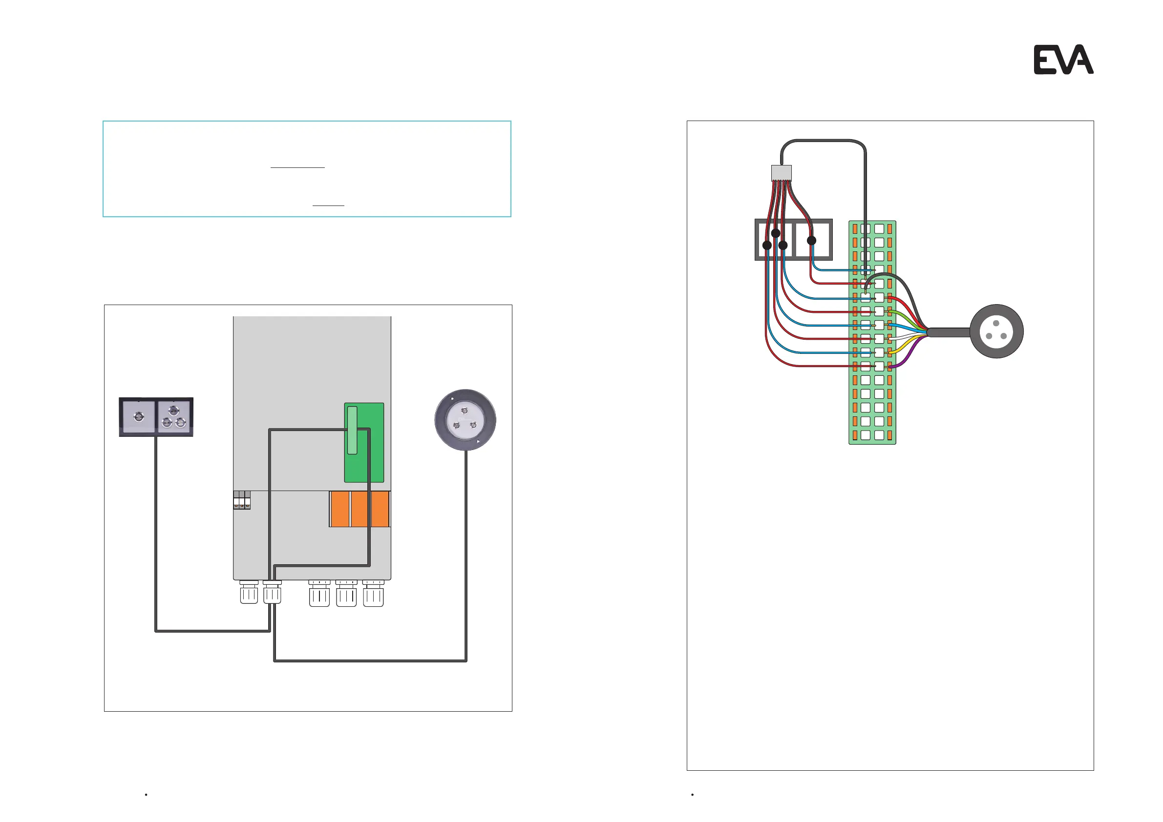
Overview of an EVA Piezo configuration (You can have one or both units)
What kind of control unit are you going to use?
EVA Piezo3 and/or EVA Piezo SQ3/SQ4: Go to step 4.2
Only the EVA experience web app?
No electrical connection is needed, go directly to step 4.3
4.2 Connect EVA Piezo to Motor Control Unit
General
l You can install only an EVA Piezo3 or SQ3/SQ4, or you can install both.
l The illustration shows the back side of the EVA Piezo SQ4.
l The buttons of the Piezo SQ3 are installed similar to the first three buttons of the
Piezo SQ4.
l You can put multiple cables into one port.
l Always check the wire coloring of the Pïezo and 12Vdc polarity before installation.
l To extend the cables always use a minimum core diameter of 0.25mm2 with a maximum
cable length of 30 metres. We recommend using cable type LiYY 16 x 0.25mm2
(Lapp Unitronic) or similar.
EVA Piezo3
l Connect the 7 wired cable from the EVA Piezo3 to the Control Print of the Motor Control
Unit on the indicated numbers.
Piezo SQ3 / SQ4
l Connect the blue and one of the red cables from the EVA Piezo SQ3/SQ4 to the Control
Print of the Motor Control Unit.
l Combine the black and the remaining red cables from the EVA Piezo SQ3/SQ4 and
connect to the Control Print of the Motor Control Unit. Group the wires 7, 9, 11, 13, 15, 17, 19,
and 21 to the Piëzo 4 switch, sw 9 (always use a cable with a minimum core diameter of
0.5mm
2
).
8
10
1 2
3 4
5 6
7
9
11 12
13 14
15 16
17 18
19 20
21 22
23 24
25 26
27 28
29 30
31 32
8
10
12
14
16
18
20
22
1
2
3
4
Electrical connections on the control print of the Motor Control Unit