EVCO S.p.A.
EV3 MVC & EVD MVC | Application manual ver. 1.0 | Code 144EV3MVI104
page 10 of 72
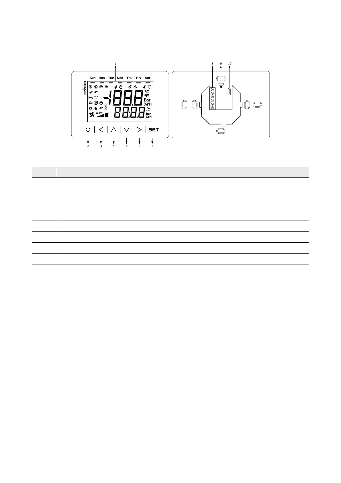
2.4 Description of EVJ LCD
The diagram below shows the layout of the EVJ LCD remote keypad for wall installation in 111.4x76.4 mm format.
The table below describes each part of the EVJ LCD.
Part Description
1 Multi-functional display
2 On/Off key, subsequently also called the On/Stand-by key
3 Left key, subsequently also called the Left key
4 Increase key, subsequently also called the Up key
5 Decrease key, subsequently also called the Down key
6 Right key, subsequently also called the Right key
7 Setting key, subsequently also called the Set key
8 Screw terminal block for cabling for the power supply and the INTRABUS port
9 unused
10 unused
The table gives the maximum provided.