EVCO S.p.A.
EV3 MVC & EVD MVC | Application manual ver. 1.0 | Code 144EV3MVI104
page 20 of 72
5.3 Description of connectors
Description of connectors for EV3 MVC
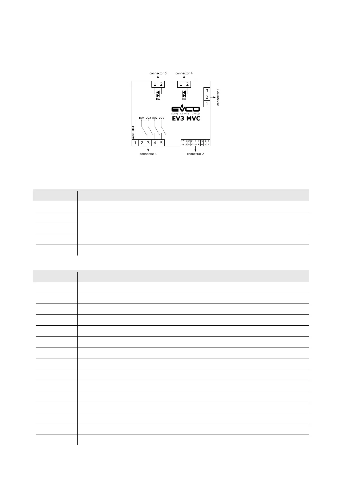
The picture below shows the layout of the EV3 MVC connectors.
The tables below describe the EV3 MVC connectors. The tables give the maximum provided.
Connector 1
Part Description
1 relay digital outputs DO1... DO4 (max. 10 A): common
2 relay digital output DO4 (3 A SPST): normally open
3 relay digital output DO3 (3 A SPST): normally open
4 relay digital output DO2 (3 A SPST): normally open
5 relay digital output DO1 (3 A SPST): normally open
Connector 2
Part Description
1 Analogue input IN6
2 Analogue input IN1
3 Analogue input IN7
4 Analogue input IN2
5 Dry contact digital input/pulse input IN8
6 Analogue input IN3
7 Dry contact digital input/pulse input IN9
8 Analogue input IN4
9 Dry contact digital input IN10
10 Analogue input IN5
11 Analogue output AO1
12 reference (GND)
13 Analogue output AO2
14 INTRABUS port signal:
15 Output 12 VDC, max. 40 mA