EVCO S.p.A.
EV3 MVC & EVD MVC | Application manual ver. 1.0 | Code 144EV3MVI104
page 8 of 72
2.2 Description of EVD MVC and EVD EXP
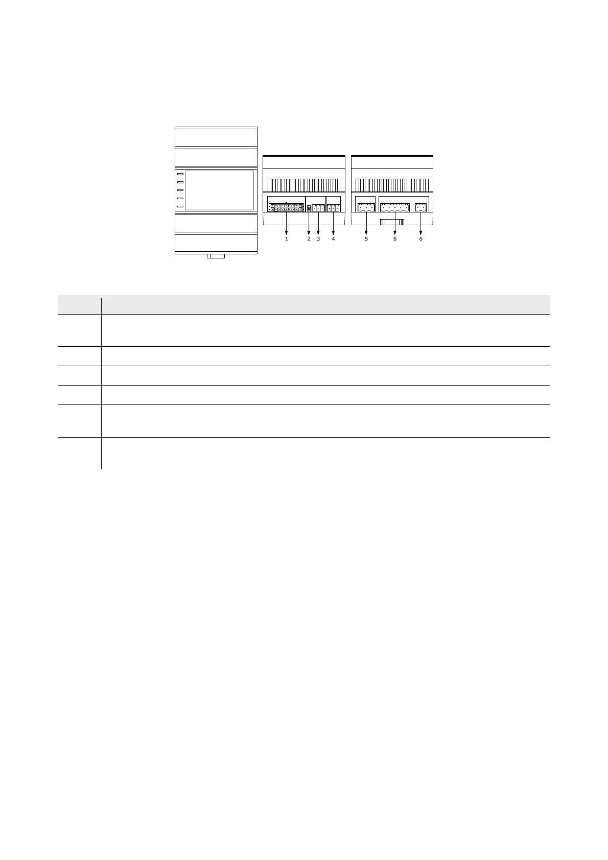
The diagram below shows the layout of the EVD MVC and EVD EXP controller and I/O expansion for installation in an electrical
switchboard on a DIN rail in standard 4 DIN-module format.
The table below describes each part of the EVD MVC.
Part Description
1
Male Micro-Fit connector for cabling for analogue inputs, digital inputs, analogue outputs and the open collector digital
output (for future reference, the digital output OC1)
2 Micro-switch for the termination resistor for the RS-485 MODBUS line (not available for EVD EXP)
3 Plug-in screw terminal block, male only, for cabling for the RS-485 MODBUS port (not available for EVD EXP)
4 Plug-in screw terminal block, male only, for cabling for the INTRABUS port
5
Plug-in screw terminal block, male only, for cabling for the digital outputs with electro-mechanical relay (for future
reference, the digital outputs DO1 and DO2)
6
Plug-in screw terminal block, male only, for cabling for the power supply, electrical-mechanical relay digital outputs (for
future reference, the digital outputs DO3 and DO4)