6
Installation (continued)
4
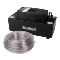
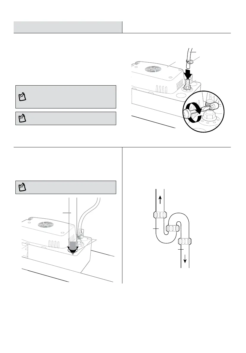
Attaching tubes to the pump
□
Attach 3/8” clear vinyl tubing (2) to the check valve (1).
□
Secure with a 1/2” hose clamp (3) (not included).
□
Route the tubing up and away from the condensate pump (A).
□
Avoid compressing or kinking the tube.
NOTE: The tube route should be the shortest possible
distance from the pump to the building exterior or other
drain location. For best results, the distance that the water
must go UP should be shorter than the distance that it goes
DOWN.
A
1
3
2
5
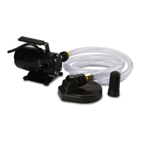
Installing the drain tubes
□
Install the condensate drain tubing (1) (not included) into
one of the four inlet holes (2), making sure the tubing is
straight.
2
1
6
Install a “P” trap
□
To Condensate pump (A)
To condensing
furnace or humidifier
Condensate
drain tubing
“P” trap
NOTE: Check local codes for water discharge
requirements.
NOTE: When using rigid tubing such as PVC, the bottom
should be cut to a 45º angle.
If installing to a condensing furnace or humidifier, a “P” trap
(not included) should be used. This will prevent air or incidental
steam contact with the pump as this pump is UL rated for
temperatures only up to 140ºF.
MOC.TOPEDEMOH 7
.ecnatsissa rehtruf rof 77-528-38788-1 tcatnoc esaelP
Installation (continued)
7
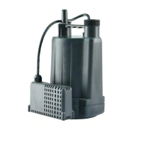
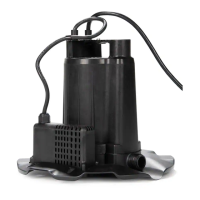
Attaching the pump inlet covers
□ Attach the pump inlet covers (B) to the remaining
condensate pump (A) inlet holes.
NOTE: Covering inlet holes prevents the condensate
pump (A) from collecting debris or insects.
B
A
8
Attaching the wires
WARNING: Risk of electrical shock! Ensure that power
to the A/C unit / furnace and the pump is shut off before
attempting this step! Failure to follow these warnings will
void the warranty and could result in a fatal electric shock.
□
in the wiring diagram. If the wiring is not present from
the air conditioner, contact HVAC professional (optional,
advanced).
NOTE: A pump safety switch should be used on
24V Class II control circuits only.
SYSTEM
T-STAT
Com
Run
OVEFLOW SWITCH
24V 1A Max
R W G Y
R W G Y
Typical Thermostat
Typical Thermostat
Connections of Appliance
Wires from
air conditioner
(if present)
C
9
Connecting the power
WARNING: Risk of electrical shock! This pump must be
properly connected to power following the National Electric
Code (NEC). Never cut the cord or ground plug. Failure to
follow these warnings will void the warranty and could
result in a fatal electric shock.
□ Plug the condensate pump (A) into a properly grounded
3-prong 120 volt ground fault circuit interrupter (GFCI)
outlet. A green LED (1) will indicate if power is available.
NOTE: Do not plug the condensate pump (A) into an
extension cord or connect to a power source that may be
inadvertently or automatically turned off.
1