L
Lisa DayJul 29, 2025
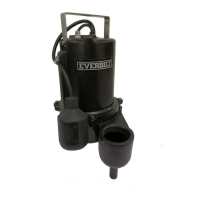
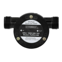
What to do if Everbilt EB-PUMP-T Water Pump doesn't start when full of condensate?
- SScott SmithJul 29, 2025
If your Everbilt Water Pump doesn't start when it's full of condensate, there are a couple of things you can check. First, make sure the pump is getting power; a green LED indicator on the pump cover should be lit. If there's power, the next thing to check is the impeller. Clear any blockages in the impeller housing. If it still doesn't work, the motor might be stuck, and you'll need to contact the manufacturer since there are no user-serviceable parts.