59
Electrical System
6.4 Switch & Circuit Breaker Panels
Ignition Switch Panels
Ignition switch panels are unique to each engine
manufacturer and the engine control options
selected. Your dealer will provide you with the
proper starting procedure for your boat at the time
of delivery. Additional information for the ignition
switch system installed in your boat is located in
the engine and control system operating manuals
included in your information packet.
Yamaha Command Link Plus
®
Ignition
Most Everglades boats are equipped with Yamaha
engines and the Command Link or Command Link
Plus
®
ignition key panels that oer the latest in
technology and durability.
The ignition switch is a key activated switch, lo-
cated near the helm below the steering wheel,
which starts and stops the engine. The switch
has OFF - ON and momentary START positions.
Starting procedure
Make sure the engine is down with the shift lever in
the neutral position and your hand on the control
lever. Turn the ignition key to the ON position to
activate the fuel pump and ignition system. Wait
5 seconds for the fuel pump to pressurize the sys-
tem, then turn the key to the start position. When
the engine starts, release the key and the switch
will automatically go to the run position. Stop
the engine by turning the key to the OFF position.
The engine ignition circuits are protected by fuses
or circuit breakers located on each engine.
Helm Master Ignition
Some single engine boats are equipped with the
Helm Master ignition panel that oers the latest
technology and security. This is a “keyless” elec-
tronic panel which energizes the ignition system of
multiple outboards with only one Radio Frequency
ID key by touching the panel with the electronic
key Fob. The panel features lights which indicate
when the engines are running and a START/STOP
button for each engine. For convenience and
protection, engines can not be restarted while
running.
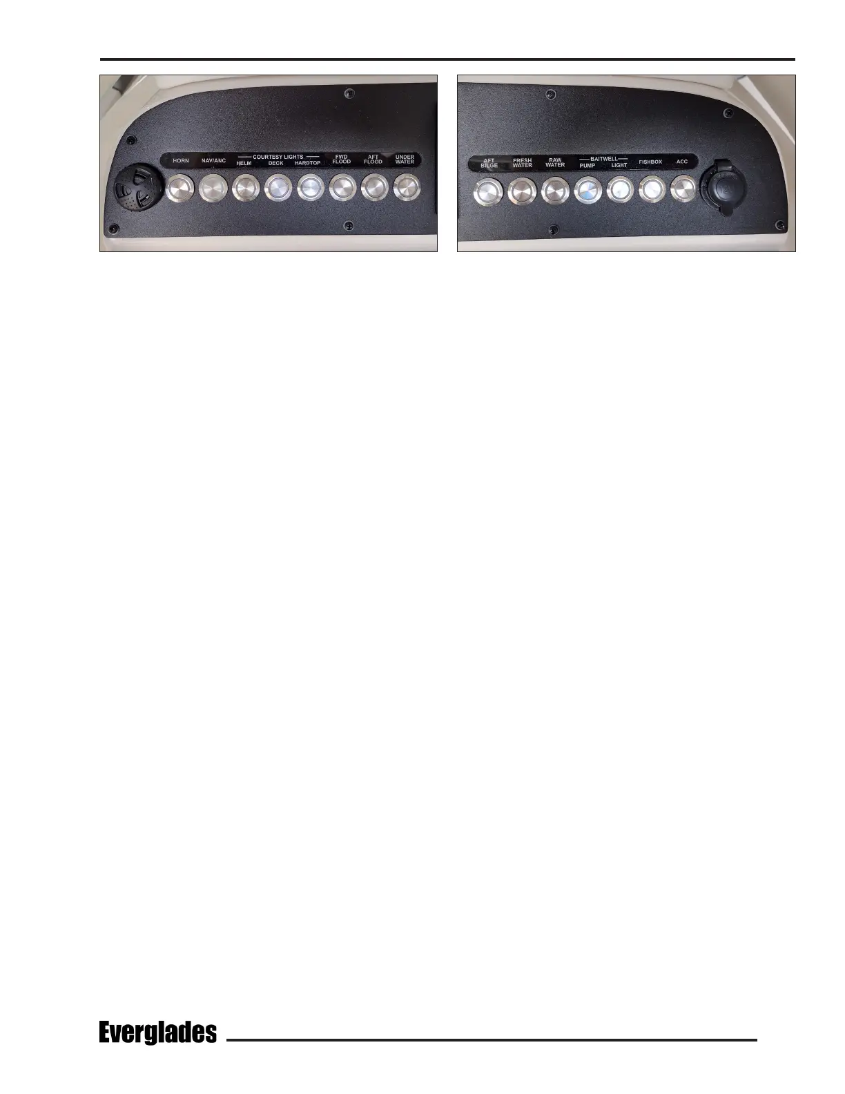
Helm Accessory Switch Panel
The main accessory switch panel is located at the
helm. The circuit breakers that protect the ac-
cessories are built into the switches. An LED light
built into the switches indicates that the circuit is
activated.
The following is a description of the accessories
typically controlled by the main accessory switch
panel:
Horn
A momentary switch that activates the boat horn.
Aft Bilge
Activates the aft bilge pump located in the stern
bilge near the transom. The pump moves water
out a thru-hull tting in the hull. When pumping
is complete, move the switch to the OFF position
to turn the pump o.
When the switch is o, the pump is controlled by
an automatic oat switch that is activated when-
ever the batteries are connected. The pump will
run as needed whenever the water in the bilge
accumulates high enough to raise the oat switch
to the ON position and turn o when the water
is removed.
Port Helm Switch Panel Starboard Helm Switch Panel