33
5 ELECTRIC CONNECTIONS
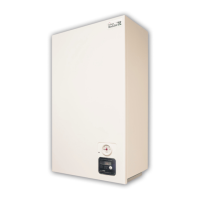
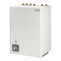
MODUSAT TP requires a 230/240V mains connection.
Before attempting any installation, repair or maintenance work remove the
electric supply line, possibly with an external switch.
Follow the instructions below to connect the electric power supply to the unit:
cover pipes and cables in order not to damage them
use cables of suitable size for electric connections
ask a qualified technician to check the electric wiring because the
manufacturer/supplier is not responsible for possible damage due to missing earth
connection or any other anomalies.
check also that the supply line is adequate for the maximum electric power needed and
indicated on the label. Make also sure that the cable size is correct and in any case not
less than 1.5 mm²
An efficient earth connection is essential to guarantee the safety against electric shocks.
The unit is supplied with a 3 pole cable to be connected to 230/240Vac – 50Hz supply.
Make sure to identify the earth wire and connect it to the relevant earth point.
Important! The connection to the electric power supply line must be fixed (no plugs), a
fused switch (6A – 3mm gap min) must also be used to break the supply.
In case it’s required to change the supply cable, refer to qualified personnel.
Extension cords, multiple plugs, and other adapters are not allowed.
It is FORBIDDEN to use the circuit pipes to earth electric connections.
The unit is not protected from lightning.
5.1 Auxiliary connections
Don’t connect the mains power supply to the Room Unit, it would destroy it!
Use the relevant 4 pole connector and a suitable 4 wire shielded cable (4x0,35 mm
2
)
for this connection and follow the procedure indicated below
Remove the electric supply to the unit using the external switch
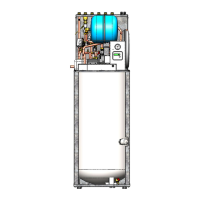
Remove front panel
Remove then the screw blocking the electric box and swivel it
Now you can access the high and low voltage connectors