EvoHeat Evo270 Hot Water Heat Pump Manual
5. Installation
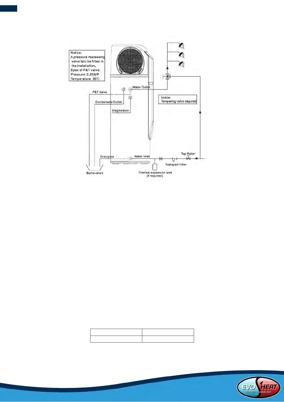
5.1 Pipeline Connection Diagram
Pipeline connection explanation
Installation of the water inlet or outlet pipes: The specification of the water inlet and outlet threat is BSP3/4(internal
thread). Pipes must be heat-resistant and durable.
Installation of the pipe for P&T valve: The spec of the valve connecting thread is BSP3/4(internal thread). After
installation, it must be confirmed that the drainpipe outlet is exposed in the air. When the flexible drainpipe is joined
to the pressure relief orifice of this valve, you must ensure that the flexible drainpipe is pointing downwards and
exposed in the air.
ATTENTION
The P&T valve attached with the unit must be installed. Failure to do so will cause damage to the unit and possible
personal injury.
Do not use stainless steel fittings to connect directly with other metals to prevent galvanic corrosion.
Drain the water tank through the drain valve at the bottom part of the unit.
5.2 Recommended Household Size
The below recommendations are based on heat pump only mode.
Higher occupancy levels are able to be achieved with the Hydroboost heater activated.
Notice: High usage of hot water and other factors could affect this recommendation. Please consult your supplier if you have
special requirements.