BEVEL ANGLES (0
0
AND 45
0
)
0
0
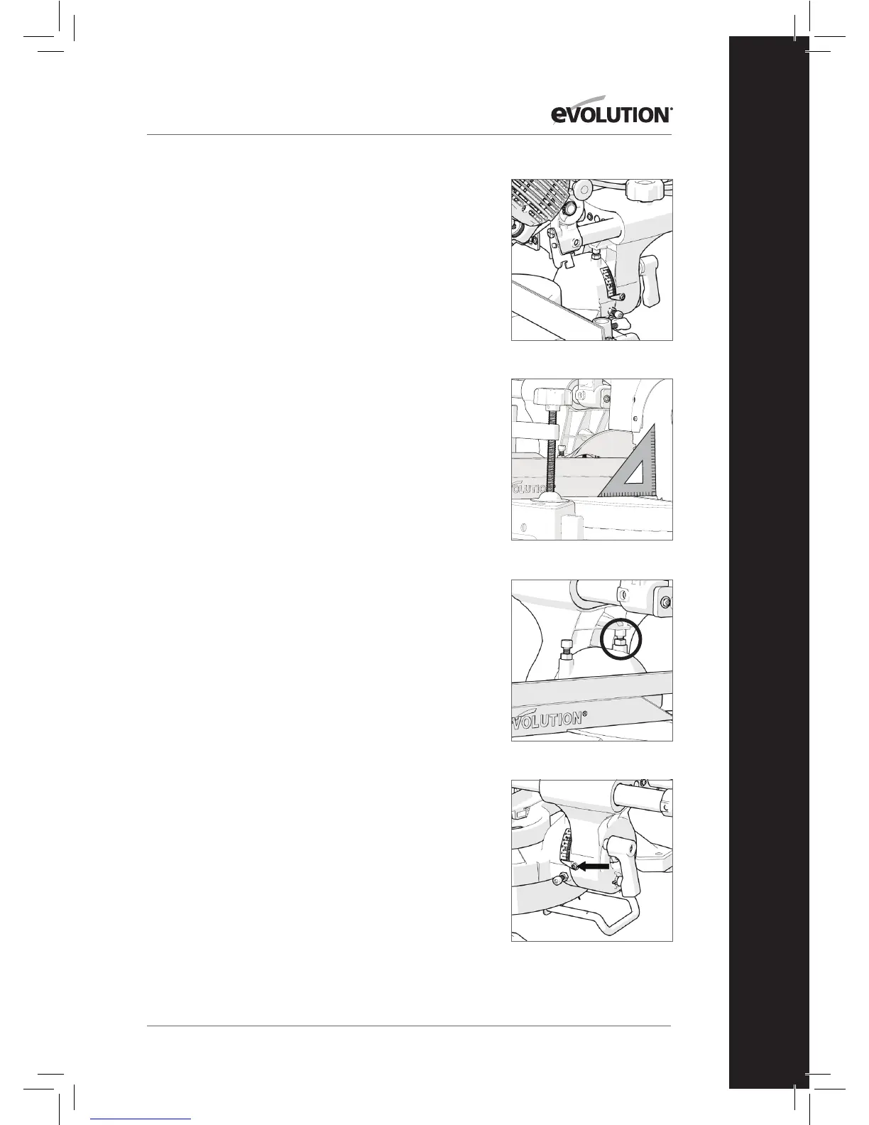
Bevel Stop Adjustment
• Ensure that the Cutting Head is in the locked down position
with the latching pin fully engaged in its socket.
• Ensure that the Cutting Head is upright, against its stop and
the bevel pointer is indicating 0
0
on the scale. (Fig. 12)
• Place the Set Square on the table with one short edge
against the table and the other short edge against the blade
(avoiding the TCT tips). (Fig. 13)
• If the blade is blade is not 90
0
square with the mitre table
adjustment is required.
• Loosen the Bevel Lock Handle and tilt the Cutting Head to
the left.
• Loosen the locknut on the Bevel Angle Adjustment Screw.
(Fig. 14)
• Use a Hex Key to turn the screw in or out to adjust the blade angle.
• Return the Cutting Head to its upright position and recheck
the angular alignment against the Set Square.
• Repeat the above steps until correct angular alignment
is achieved.
• Tighten the Bevel Angle Adjustment locknut securely.
0
0
Bevel Pointer Adjustment
Note: The operator must be satisfied that the blade is set
exactly perpendicular to the table when in the upright position
and against its stop.
• If the pointer is not in exact alignment with the 0
0
mark on
the protractor scale adjustment is necessary.
• Loosen the Bevel Pointer screw using a #2 Phillips
screwdriver. (Fig. 15)
• Adjust the Bevel Pointer so that it is in alignment exactly with
the 0
0
mark.
• Retighten the screw.
Fig. 12
Fig. 13
Fig. 14
Fig. 15
25
www.evolutionpowertools.com
EN