5.7. GPIOConnections
5.7.1. GP In Connections
GPI Triggers
The allocation of the XTnano server GPI triggers is performed in the Multicam
Configuration window, in the GPI tab. See the Configuration manual for detailed
information on allocating GPI triggers.
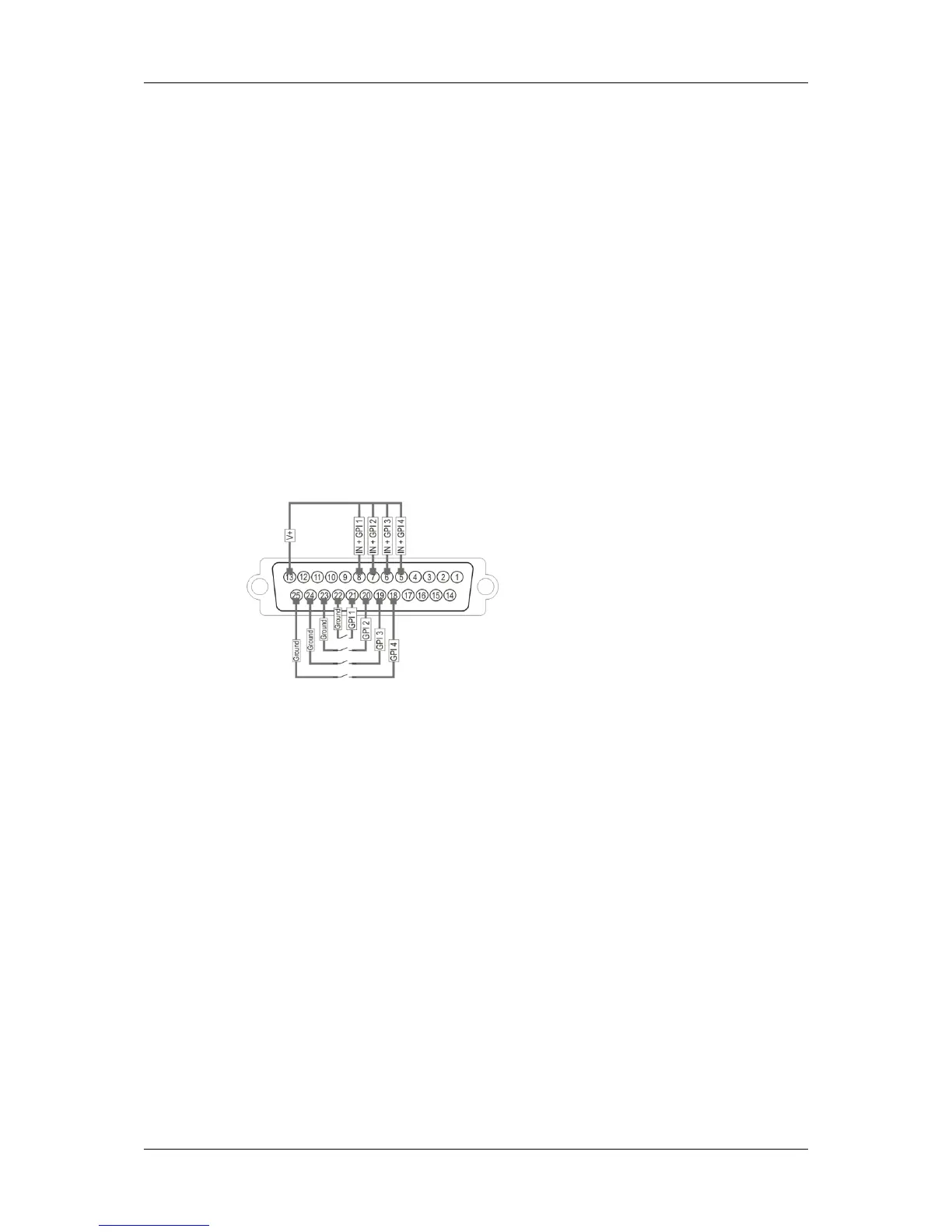
Opto isolated Inputs (GP In 1, 2, 3, 4)
Pin-Out
Specifications
• The input consists in an opto diode (VF @ 1.1 Volt) in series with a 470 ohm resistor.
• Typical switching point @ 1.4 mA, for secure operation:
◦ i=0 to 0.5 mA -> opto OFF
◦ i=2.5 to 30 mA -> opto ON
◦ imax= 30 mA
• Direct connection to a TTL/CMOS signal possible (Pin opto - to GND and pin opto + to
the TTL/CMOS signal).
Typical switching point @ 1.6 Volts, for secure operation:
◦ Vin< 0.8 Volts -> opto OFF
◦ Vin> 2.2 Volts @ 2 mA -> opto ON
◦ Vin max (without external resistor) = 15 Volts
38 5. Hardware Installation and Cabling
EVS Broadcast Equipment SA Issue 12.02.A- December 2013


![Preview: EVS XT[2]](https://data.easymanua.ls/products/617905/200x200/evs-xt-2.webp)


