6.2.2. CODConnectivity in SD and HD
Connector Assignments
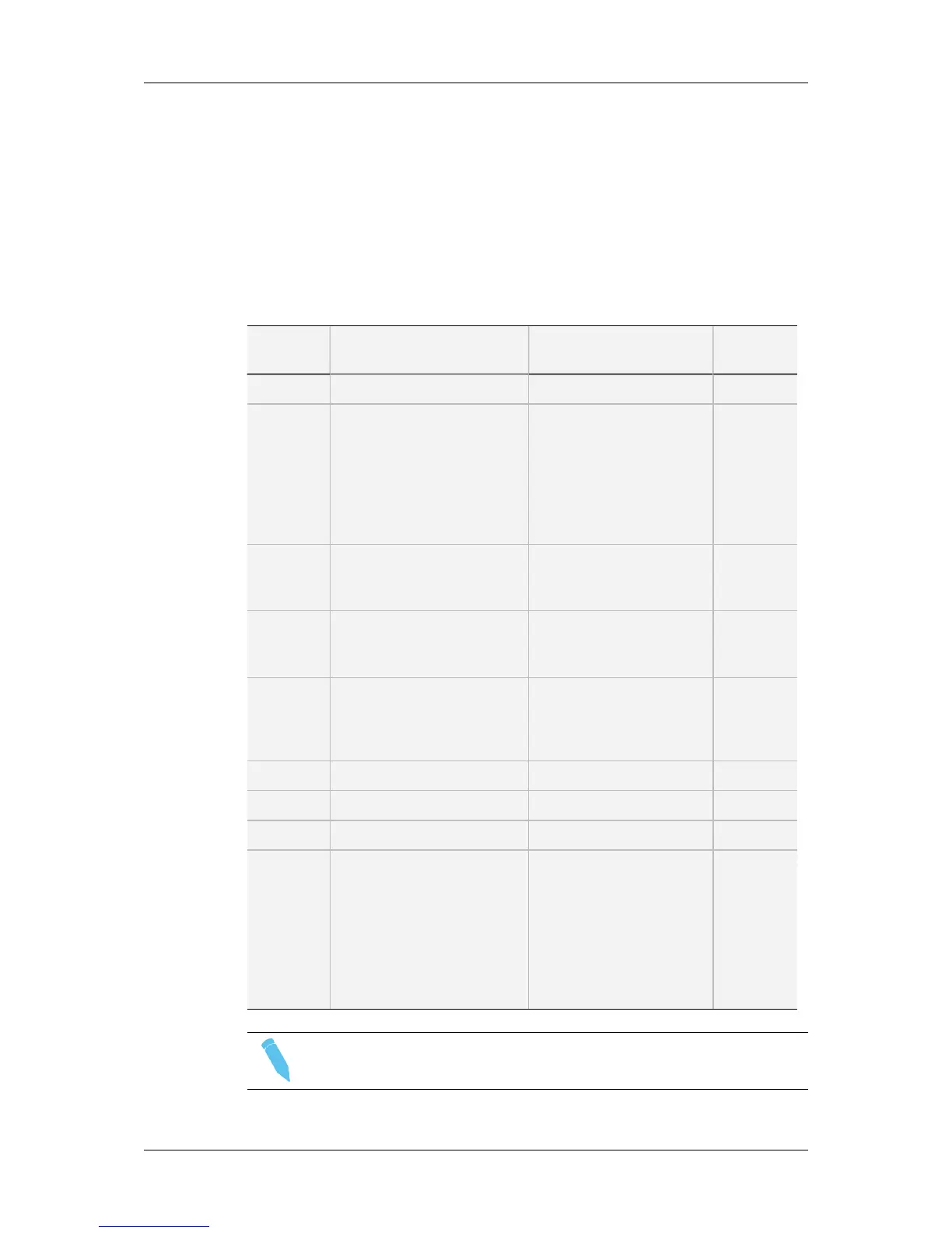
This section describes the connector assignments and layout for the video standards SD
525i, SD 625i, HD 1080i and HD 720p.
The specific connectivity for HD 3D Dual Link is described in the following sections.
Connector SD mode HD mode
Connector
label
J1 Not used Not used CHAR SD
J2 SDI monitoring output (SD) SDI monitoring output
(HD)
Not wired
to the
backplane.
Used for
onboard
multiviewer
input.
J3 Loop-through for the SDI
input signal (SD)
Loop-through for the SDI
input signal
(SD, down-converted)
OUT B
J4 SDI monitoring output (SD) SDI monitoring output
(SD/HD)
CHAR
OUT
SD/HD
J5 Not used
or
SDI input (SD) in an XREC
configuration
Not used
or
SDI input (HD) in an XREC
configuration
IN B
J6 SDI program output HD SDI program output OUT
J7 Not used Not used OUT
J8 SDI input (SD) HD SDI input (HD) IN
J9 Alternate SDI input
(SD, for the internal loop)
Alternate HD SDI input
(HD, for the internal loop)
Not wired
to the
backplane.
J9 of
REC1 only
connected
to Loop
connector.
Note
The loops of the input signal are not genlocked.
46 6. Boards Description
EVS Broadcast Equipment SA Issue 12.02.A- December 2013


![Preview: EVS XT[2]](https://data.easymanua.ls/products/617905/200x200/evs-xt-2.webp)


