5.7. GPIOConnections
5.7.1. GPIO Connector Pin-Out
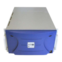
The following table lists the GPIO connector pin-out:
1 Relay Out 4 14 Relay Out 4
2 Relay Out 3 15 Relay Out 3
3 Relay Out 2 16 Relay Out 2
4 Relay Out 1 17 Relay Out 1
5 IN + opto 4 18 IN - opto 4
6 IN + opto 3 19 IN - opto 3
7 IN + opto 2 20 IN - opto 2
8 IN + opto 1 21 IN - opto 1
9 I/O TTL 8 22 GND (Return I/O 8)
10 I/O TTL 7 23 GND (Return I/O 7)
11 I/O TTL 6 24 GND (Return I/O 6)
12 I/O TTL 5 25 GND (Return I/O 5)
13 + 5V 50mA max.
5.7.2. GP In Connections
GPI Triggers
The allocation of the XTnano server GPI triggers is performed in the Multicam
Configuration window, in the GPI tab. See the Configuration manual for detailed
information on allocating GPI triggers.
XTnano Server- Version 11.01- Hardware Technical Reference Manual
5. Hardware Installation and Cabling 29


![Preview: EVS XT[2]](https://data.easymanua.ls/products/617905/200x200/evs-xt-2.webp)


