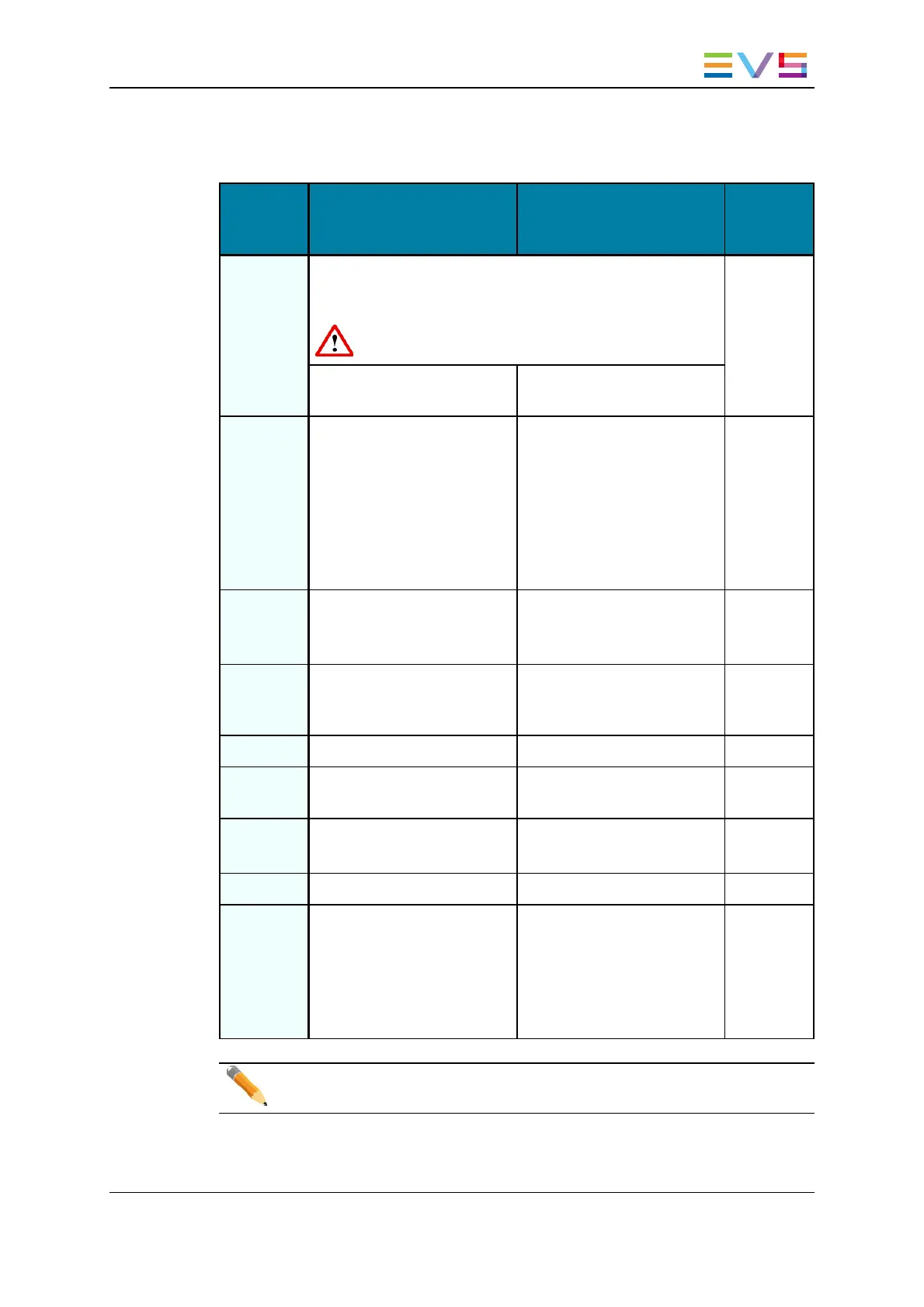
Connector Assignments
Con-
nector
SD mode HD mode
Con-
nector
label
J1 J5 is factory-wired to the backplane instead of J1. You can
connect J1 instead of J5 if CVBS monitoring is required in
SD or HD mode.
SDI monitoring is no longer available on J1.
CHAR SD
CVBS monitoring output
(SD)
CVBS monitoring output
(SD, down-converted)
J2 SDI monitoring output (SD) SDI monitoring output
(SD, down-converted)
Not wired
to the
backplane.
Used for
onboard
mul-
tiviewer
input.
J3 Loop-through for the SDI
input signal (SD)
Loop-through for the SDI
input signal
(SD, down-converted)
OUT B
J4 SDI monitoring output (SD) SDI monitoring output
(SD/HD)
CHAR
OUT
SD/HD
J5 Not used Not used IN B
J6 SDI program output
(SD, identical to J7)
HD SDI program output
(HD, identical to J7)
OUT
J7 SDI program output
(SD, identical to J6)
HD SDI program output
(HD, identical to J6)
OUT
J8 SDI input (SD) HD SDI input (HD) IN
J9 Alternate SDI input
(SD, for hardware loop)
Alternate HD SDI input
(HD, for hardware loop)
Not wired
to the
backplane.
Used for
internal
loop in.
Note
The loops of the input signal are not genlocked.
XTnano Server- Version 11.01- Hardware Technical Reference Manual
6. Boards Description 39


![Preview: EVS XT[2]](https://data.easymanua.ls/products/617905/200x200/evs-xt-2.webp)


