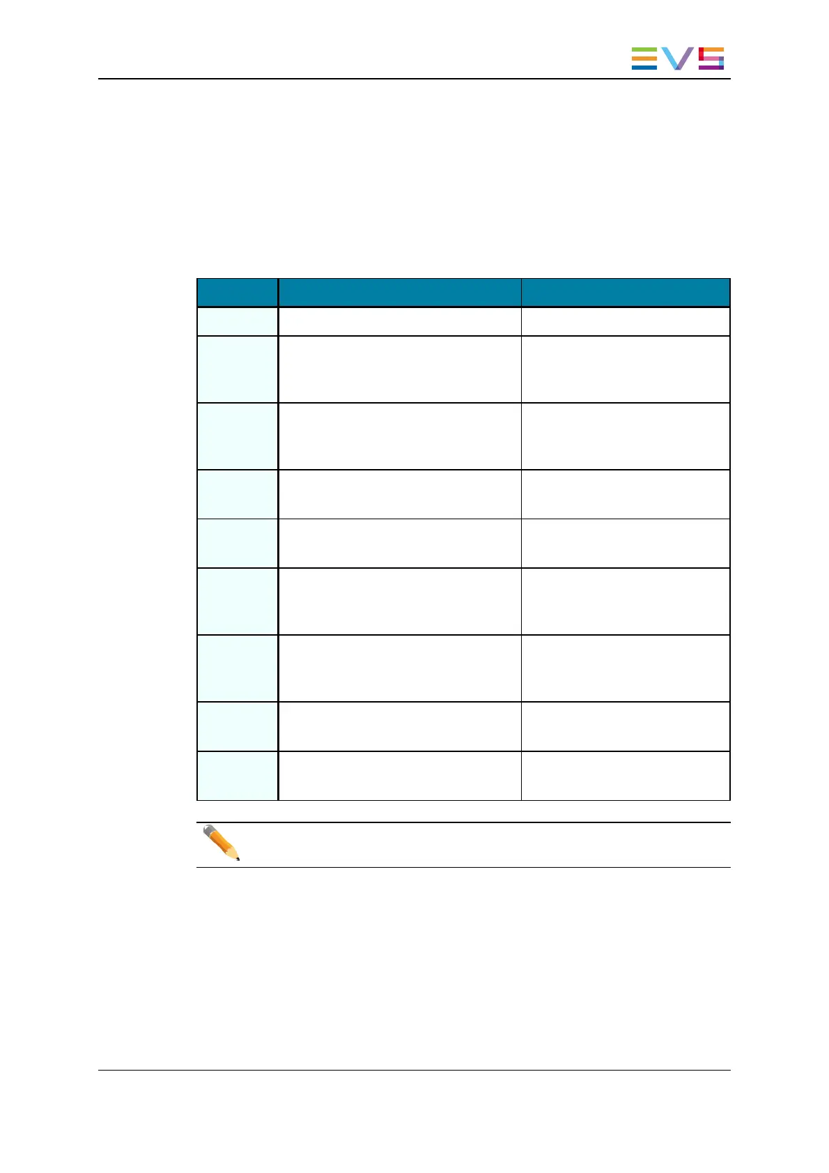
6.2.3. CODConnectivity in 3D Dual Link
This section describes the connector assignments and layout for the video standards HD
3D in Dual Link mode.
Connector Assignments
Connector 3D mode Connector label
J1 N/A CHAR SD
J2 SDI monitoring output
(SD, down-converted)
Not wired to the backplane.
Used for onboard multiviewer
input
J3 HD SDI program output for right eye
(3D)
(HD)
OUT B
J4 SDI monitoring output for left eye (3D)
(HD/SD)
CHAR OUT SD/HD
J5 HD SDI input for right eye (3D)
(HD)
IN B
J6 HD SDI program output for left eye
(3D)
(HD, identical to J7)
OUT
J7 HD SDI program output for left eye
(3D)
(HD, identical to J6)
OUT
J8 HD SDI input for left eye (3D)
(HD)
IN
J9 Alternate HD SDI input
(HD, for hardware loop)
Not wired to the backplane.
Used for loop in.
Note
The loops of the input signal are not genlocked.
XTnano Server- Version 11.01- Hardware Technical Reference Manual
6. Boards Description 41


![Preview: EVS XT[2]](https://data.easymanua.ls/products/617905/200x200/evs-xt-2.webp)


