- 15 -
3.10 Install the speed control rod assembly (linkage with the yoke installed on one
end) into the end of the speed control lever located underneath the center of the
console. Insert the end of the linkage (opposite the yoke) into the end of the
speed control lever from the right hand side and fasten with a hairpin from the
bolt bag.
3.11 Connect the lower end of the speed control linkage to the speed control crank
located at the top rear of the fuel tank support. Secure with clevis pin and hairpin
from the bolt bag.
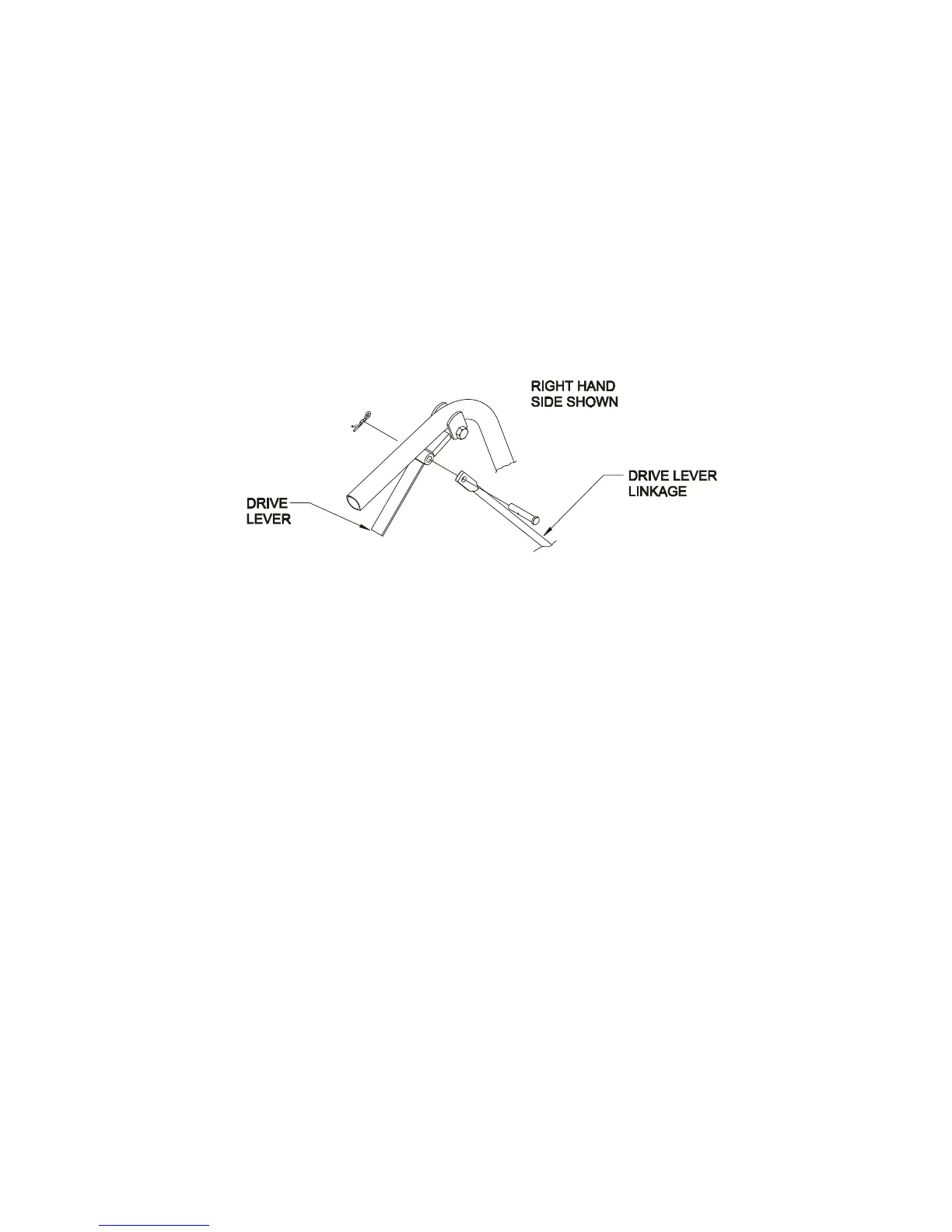
3.12 Thread each drive lever linkage into the threaded swivel. (See Figure 6).
Connect the upper end of each drive lever linkage to the drive levers. Fasten
with a long clevis pin and cotter pin from the bolt bag. Be sure the clevis pin is
first inserted through the drive linkage and then through the drive lever from the
outside before installing the hairpin cotter (See Figure 7).
NOTE: There should NOT be a washer between the neutral lock latch and
the hairpin cotter.
FIG 7
DRIVE LEVER LINKAGE TO DRIVE LEVER
3.13 Route the long unattached wiring harness lead, up the left hand side of the
handle and connect the two terminals (in any order) to the operator presence
control switch terminals underneath the control console. (On 15 & 17 HP
Kawasaki models, plug harness into back of key switch.)
Fasten the lead to the handle with two wire ties from the bolt bag, one at the
upper end of the handle next to the console, and one at the very lower end of the
handle where it attaches to the fuel tank support.
3.14 If machine is shipped without muffler installed, install muffler with hardware
provided.
3.15 For Briggs & Stratton Engine install debris guard to top of engine. (Hardware is
installed in bracket.)
3.16 Service Engine: Refer to Engine Owner’s Manual.
3.17 SERVICE BATTERY.
(Electric start units only) Machine is shipped with a dry battery.
3.17.1 Remove battery cover. Disconnect battery cables, negative (black) cable first,
and remove battery.
3.17.2 Place battery on a level surface and remove vent caps.
 Loading...