- 32 -
5.2 ADJUSTMENTS
5.2.1 Cutting height and anti-scalp roller adjustment.
WARNING
POTENTIAL HAZARD
♦ When the two front support rod hairpins are removed
from the mower deck, the weight of the tractor section
may cause the front frame to rise suddenly
WHAT CAN HAPPEN
♦ If the unit rises suddenly, injury may occur.
HOW TO AVOID THE HAZARD
♦ Securely hold down the front of the unit when the front
support rod hairpins are removed.
a) Stop engine and wait for all moving parts to stop.
b) Install hairpin clips in the holes shown on sketch below for the desired
cutting height (See Figure 11).
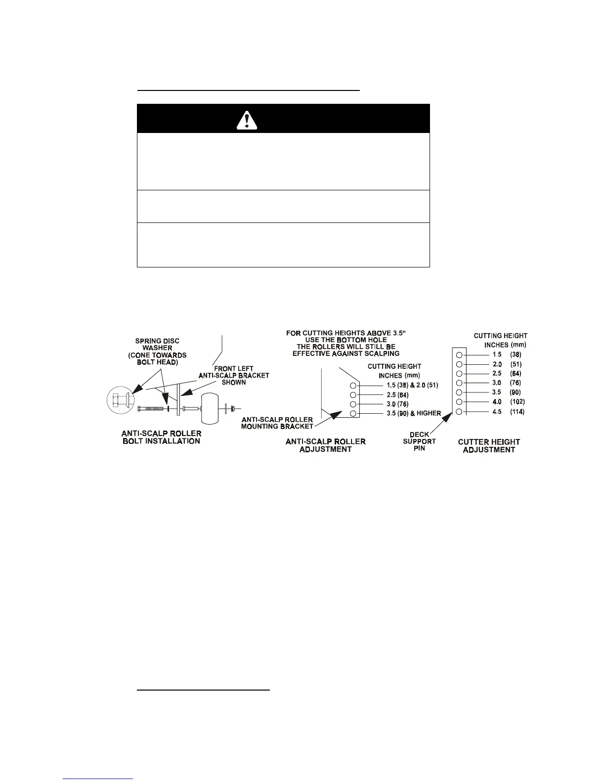
FIG 11
ANTI-SCALP ROLLER BOLT INSTALLATION
ANTI-SCALP ROLLER AND CUTTING HEIGHT ADJUSTMENT
c) Adjust anti-scalp rollers For Normal Operating Conditions. Place rollers in
one of the positions shown in Fig. 11. Rollers will maintain 3/4 in. (19 mm)
clearance to the ground to minimize gouging and roller wear or damage.
For Maximum Deck Flotation,
place rollers one hole position lower.
Rollers should maintain 1/4 in. (6.4 mm) minimum clearance to ground.
Do
Not
adjust rollers to support the deck. Be sure roller bolts and nuts are
installed with the spring disc washer between head of the bolt and
mounting bracket.
Torque to 40-45 ft-lbs., or loss of roller may result
.
d) When operating in extremely rough conditions it may be necessary to
position the anti-scalp rollers one or two holes higher than described in
"b" to prevent damage to the rollers and/or bolt failure (See Figure 11).
NOTE:
When anti-scalp rollers are placed in these positions, reduced
deck flotation will result.
5.2.2 Blade engagement Linkage: Located between the blade engagement lever on
the left handle and the left rear corner of the engine deck.
a) Stop engine and wait for all moving parts to stop.
 Loading...