- 17 -
3.17.7 Place battery back on battery stand. Connect battery cables -
positive (red)
cable first
, then the negative (black) cable. Slip insulator boot over the positive
terminal. Place cover over battery. Secure with battery hold downs.
DO NOT
overtighten.
NOTE:
If time does not permit charging the battery, or if charging equipment is
not available, follow steps 3.17.1 through 3.17.4 and install as described in
3.17.7. Then run the vehicle continuously for 20 to 30 minutes to sufficiently
charge the battery.
After charging, if battery acid level has fallen, refill battery with clean drinking
water (distilled water is preferred – if available).
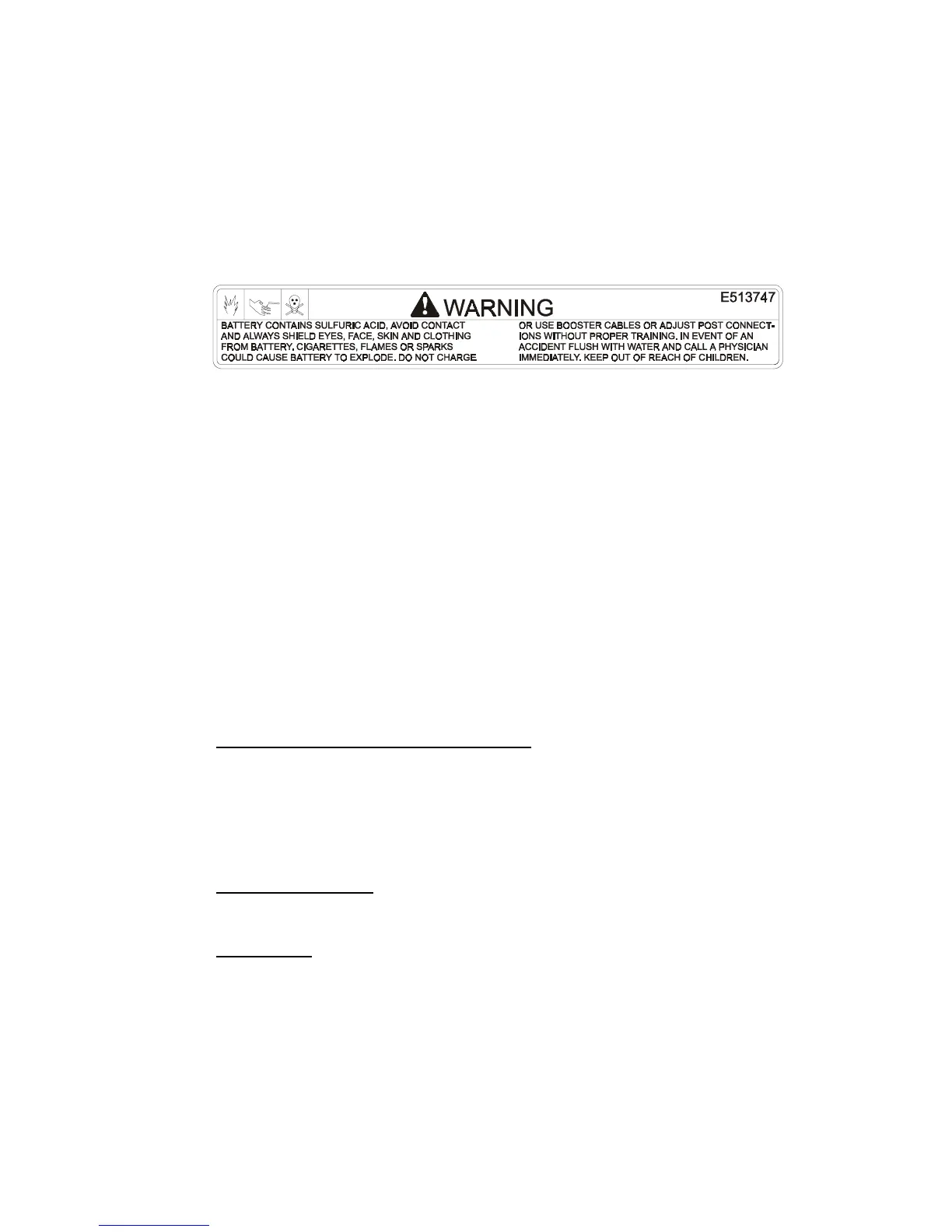
PART NO. 513747 LOCATION: Battery Cover
3.18
SERVICE HYDRAULIC OIL
The machine is shipped with hydraulic oil filled to the top of the baffle in the
reservoir. Run the machine for approximately 15 minutes to allow any extra air
to purge out of the hydraulic system. Check hydraulic reservoir and if necessary
fill the reservoir to the appropriate level with Mobil 1 15W-50 synthetic motor oil.
3.19
GREASE UNIT: NOTE:
UNIT IS NOT GREASED AT THE FACTORY.
Refer to 5.1.14, for locations and grease amounts.
3.20 Follow pre-start instructions as outlined in 4.2.
NOTE: After starting the engine and engaging the hydro drive, if either of
the drive wheels acts sluggish or will not rotate at all, stop engine and refer
to Section 5.1.10 on the Hydraulic System Air Purge procedure.
3.21 Perform any needed adjustments as outlined in the Adjustment Section.
4. OPERATION INSTRUCTIONS
4.1 Controls
4.1.1 Operator Presence Control (OPC) Levers: Located on the upperhandle
assembly directly above the handle grips.
When these levers are depressed,
the OPC system senses that the operator is in the normal operator's
position.
When the levers are released, the OPC system senses that the
operator has moved from the normal operating position
and will kill the
engine if either the speed control lever is
not in the neutral
position or the
blade clutch is engaged
.
4.1.2 Speed Control Lever: Located in middle of control console, it controls the
maximum forward speed and is infinitely variable from neutral (0 mph) to 6.2
mph.
4.1.3 Drive Levers: Located on each side of the upper handle assembly directly
below the handle grips (See Figure 8). These levers individually control the
speed and direction of each drive wheel. When the speed control lever is
moved out of the neutral position and the neutral lock latches are moved into
the drive position, as shown in Figure 8, and the drive levers are released, the
drive wheels are engaged in the forward direction.
Squeezing the left hand and/or right hand lever causes the left hand and/or right
hand drive wheel respectively to slow down, stop, or reverse, depending on how
far each drive lever is "squeezed". Squeezing the drive levers beyond the neutral
position causes the drive wheels to engage in the reverse direction regardless of
the position of the neutral lock latches and the speed control lever.
 Loading...