Maintenance
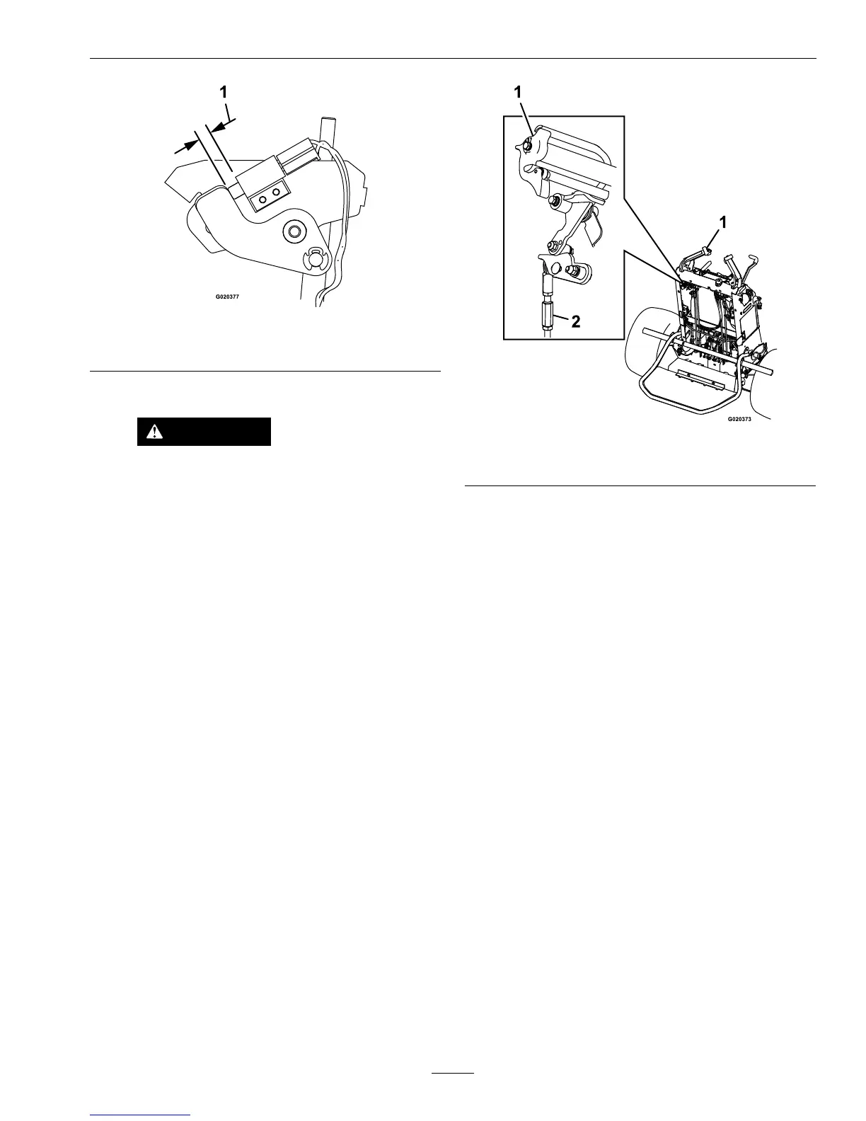
Figure34
1.11/32inch(8.6mm)
B.DriveWheelsAdjustment:
WARNING
Enginemustberunninganddrivewheels
maybeturningwhenadjustmentis
performed.Contactwithmovingpartsor
hotsurfacesmaycausepersonalinjury.
Keepngers,hands,andclothingclearof
rotatingcomponentsandhotsurfaces.
a.Starttheengineandreleasetheparking
brake.
b.Withthedriveleverrampssetand
tightened(seeAdjusttheNeutralRamp
section),placethedriveleversinthe
neutrallockposition.
c.MoveeitherOPClevertotheoperating
position.
Note:AtleastoneoftheOPClevers
mustbehelddownandtheparkbrake
mustbedisengagedwheneverthespeed
controlleverismovedoutofneutralor
theenginewillkill.
d.Pushthespeedcontrollevertothefull
forwardposition.
e.AdjustthelengthoftheLHandRH
steeringrodsuntilthewheelsarenot
turning.
Figure35
1.LHdrivelever
2.Steeringrod
f.Movethedriveleverstothefullforward
andreverseandthenbacktoneutralto
makesurewheelsarenotturning.Check
withtheneutrallocklatchesengaged.
g.Tightentherodhardware.
Important:Rodsmustbefreetopivot
onrodendballsafteradjustment.
C.SpeedControlLeverAdjustment:
a.Stopengineandwaitforallmovingparts
tostop.
b.Placethedriveleversintheneutrallock
position.
c.Loosentheupperandlowernutsonthe
speedcontrolrod(seeFigure36).
43

 Loading...