PQ2071-en-GB_V1.3 7/15
11
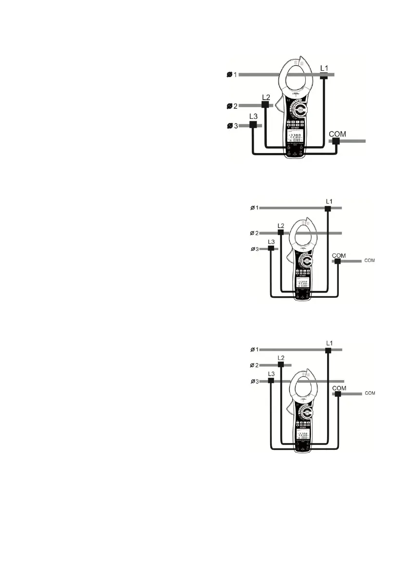
3-Phase, 4-Wire Power Measurements
1. Connect the four voltage leads as shown in
Figure. 7
2. Clamp the transformer jaw around the power
conductors connected to the L1 voltage lead.
3. Set the meter to kW. The dual display shows
the Active power kW value and the Phase
Angle (PG) value.
4. Press the L1-L2-L3 button to choose the first
phase L1 (see figure 8).
5. Press the ∑ button to save and sum the measured value
for L1. (see Figure 8)
6. Move the clamp jaw to the power conductor connected to the L2 voltage test lead.
7. Press the L1-L2-L3 button to choose the first phase
L2. The primary display shows the kW for phase L1
and the secondary display shows the Phase angle
(PG).
8. Press the ∑ button to save and sum the measured
value for L2. (figure 8). The primary display shows the
kW for phase L2 and the secondary display shows the
Phase angle (PG).
9. Move the clamp jaw to the power conductor
connected to the L3 voltage test lead.
10. Press the L1-L2-L3 button to choose the first phase L3. The primary display shows the kW for
phase L3 and the secondary display shows the Phase
angle (PG).
11. Press the ∑ button to save and sum the measured
value for L3. (figure 8)
12. After recording the kW power measurement value for
the third phase, press and Hold the
∑ button for 1 second to display the 3 phase sum of
kW on the main display and kVA on the secondary
display. (figure 9)
13. Press the ▲ button to display the 3 phase sum of
kVAR on the main display.
14. Press and Hold the ∑ button for 1 second to return to normal operation.
Figure 7