MAX300-RTG : Hardware Manual Hardware Maintenance
60
following the instructions given here. Please contact Extrel service with any
questions.
The first step to changing the inlet is to properly vent and cool the vacuum system.
Disconnect the VacTrac from the enclosure wall feed through and slide it out of the
enclosure.
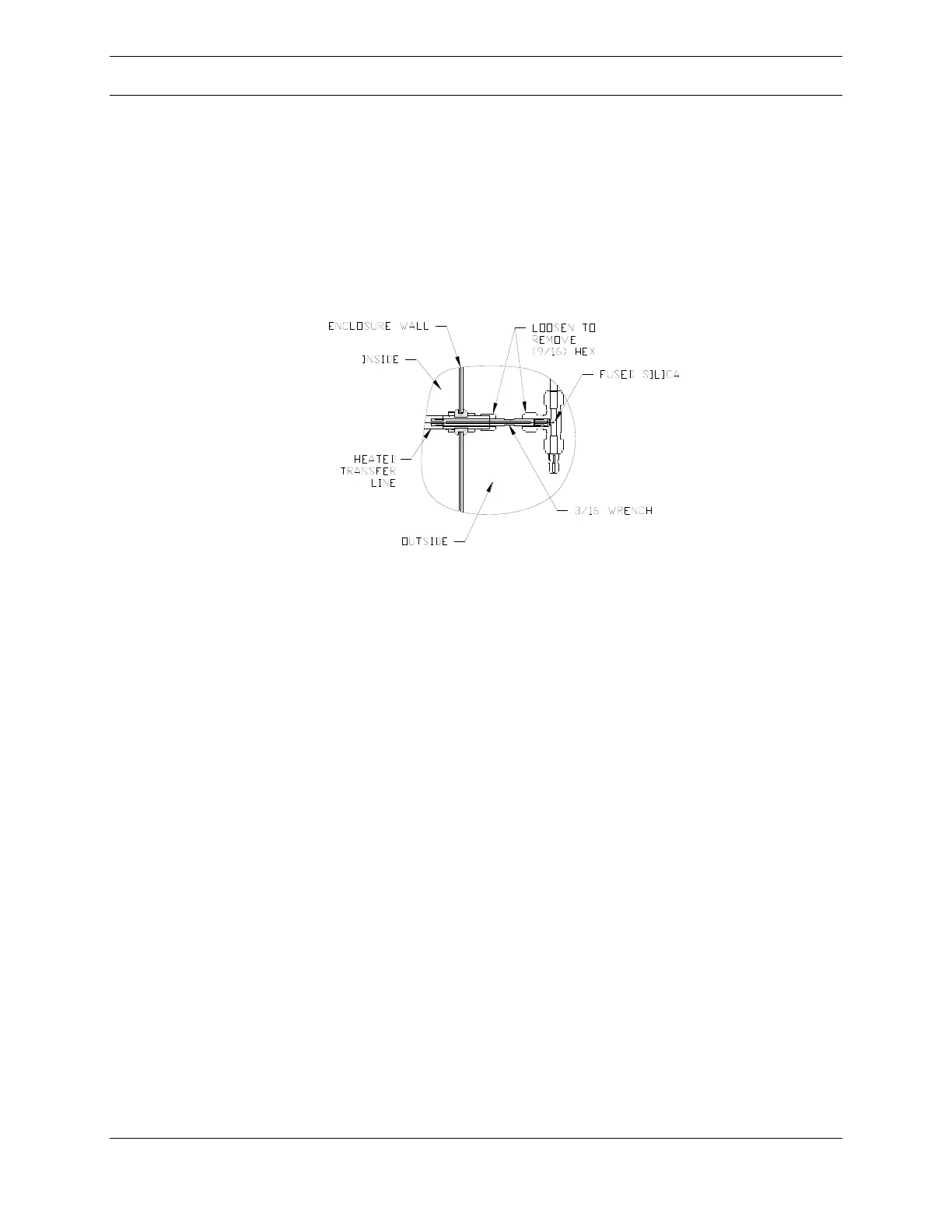
Figure 32: Inlet
The input end of the transfer line is held in place by two fitting nuts located in the
external valve enclosure. Loosen the two nuts shown in Figure 32, above, and
carefully slide the transfer line through the fitting on the enclosure wall. A short
length of the fused silica restrictor will be visible. This is the sampling point for the
mass spectrometer, so be careful to not clog or contaminate this critical region.
After sliding the VacTrac out of the enclosure, disconnect the transfer line heater’s
power and thermocouple connections. The heater power connector is located on
the chamber support structure just below and behind the ionizer flange. The
thermocouple connector is located on the back of the transfer line temperature
controller located in the same area.
Remove the inlet heater from the ionizer mounting flange. The inlet heater is
attached to the flange by four (9/64 Hex Key) screws at the base of the heater that
thread directly onto the flange, shown in Figure 33.