MAX300-RTG : Hardware Manual Hardware Maintenance
61
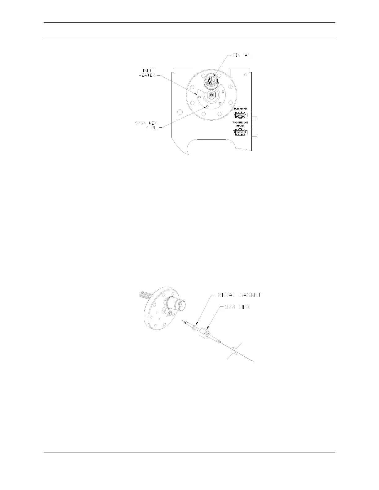
Figure 33: Inlet Mounting
Once the flange has cooled, remove the inlet by loosening the large central fitting
on the ionizer flange. The hex closest to the flange (5/8 inch) is welded on. The
outer hex nut (3/4 inch) can be rotated counterclockwise to loosen the fitting and
remove the inlet. Be careful when loosing this fitting that the wrench does not
contact the ten pin vacuum feedthrough and damage it.
Withdraw the inlet from the flange and remove the non-reusable metal gasket. A
short length of the fused silica restrictor will be visible, as in Figure 34, below. Avoid
clogging or contaminating this critical region.
Figure 34: Inlet
Verify that the replacement inlet has a new metal gasket in place. Slide the end of
the inlet into the flange fitting and tighten the nut ¼ turn past finger tight. Before
finishing the installation of the sample line, check that the new inlet is not touching
the ion region. Use an ohm meter to verify that pin “A” (refer to Figure 41, page 63)
on the ionizer feedthrough is not shorted to ground. Replace the transfer line
heater and thermocouple connectors. Reinstall the inlet heater onto the ionizer