MAX300-RTG : Hardware Manual Hardware Maintenance
76
The electrical connections can be pulled straight off the flange feedthroughs. The
multiplier is held to the flange with two 4-40 screws that can be removed with a
3/32inch hex key.
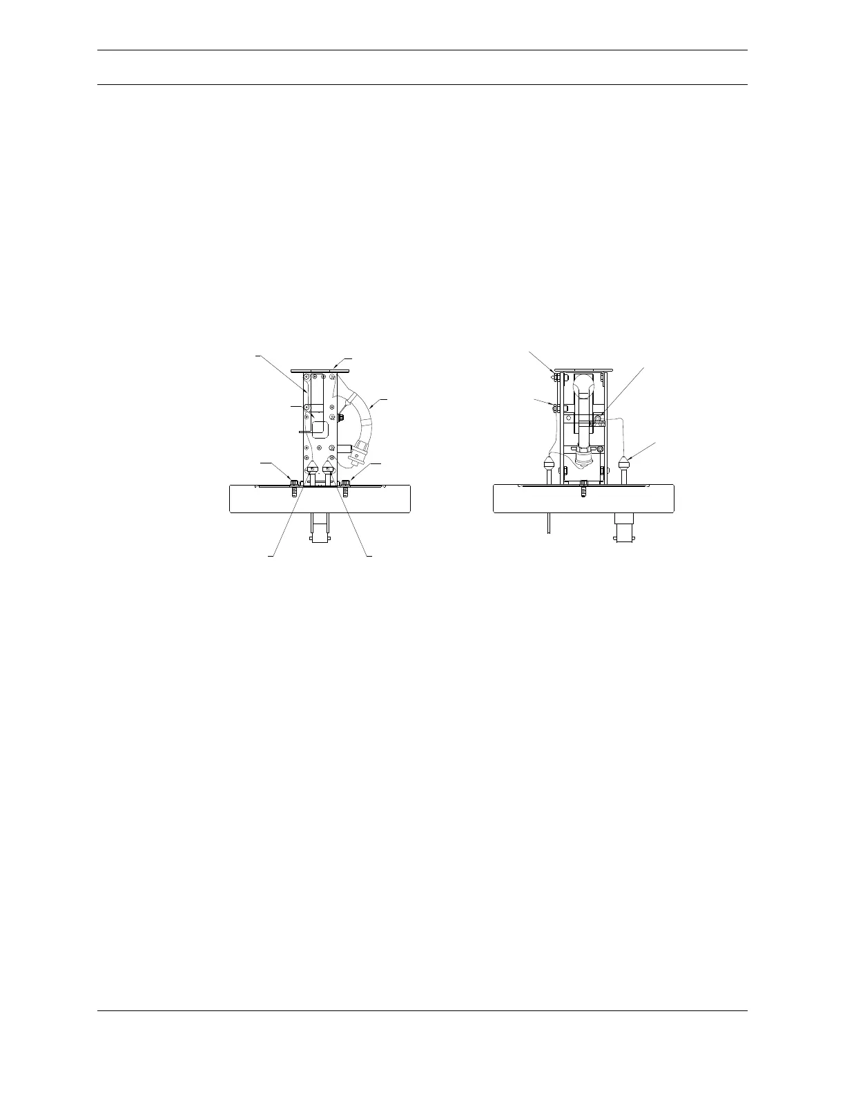
Install the new multiplier onto the flange in the same orientation as the old one
using the 4-40 screws and connect the wires to the flange feedthroughs by pushing
the connectors straight on. Refer to Figure 50, below, to verify that the wiring is
correct.
Faraday Connection
Signal Connection
4-40 Securing
Screw
Shorting Strap
FP & CD
High Voltage
Connector
Multiplier
4-40 Securing
Screw
Multiplier Tube
Faraday Plate (FP)
Conversion Dynode
(CD)
FP Connection
Point
CD Connection
Point
Multiplier HV
Connection Point
* Assembly Rotated 90 degrees
* Assembly Reference Illustration
Figure 6.13.2 Multiplier Assembly Detail
Figure 50: Multiplier Flange
Install the detector flange onto the vacuum chamber using a new 4-1/2inch copper
gasket in the same orientation it was originally. There are two threaded holes on
the flange that can be used to hold the copper gasket in place. Initially tighten the
bolts finger tight. Use an ohm meter to verify that each of the three detector
electrical leads is isolated from each other, from ground and from the quadrupole.
Note: It is normal for the high voltage connection to show 80 Megohms when
measured to ground.
Once verified that the wiring is correct, tighten the flange bolts a little at a time in a
cross pattern to keep the flanges parallel, prevent leaks, and keep the copper
gasket from becoming warped. Start the turbo and roughing pump. When both are
working correctly, attach the preamp to the flange and re-install the preamp and
multiplier HV cables.