Figure 36: Graphical Representation of a Ring Topology
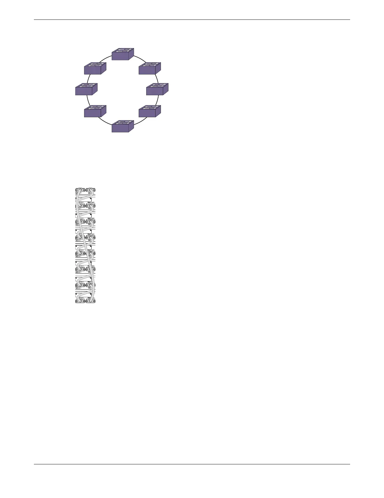
Figure 37 shows what the same ring topology would look in actual practice. Each switch in the rack is
connected to the switch above it and the switch below it. To complete the ring, a longer cable connects
Switch 1 with Switch 8.
Figure 37: Switches Connected to Each Other in a Ring Topology
Note that, while a physical ring connection may be present, a ring active topology exists only when all
nodes in the stack are active.
Daisy Chain Topology: Not Recommended for Stacking
Stackable switches can be connected in a daisy-chain topology. This is a ring topology with one of the
links disconnected, inoperative, or disabled. A daisy chain can be created when a link fails or a node
reboots in a ring topology, but the daisy chain topology is not recommended for normal operation.
Connect your stack nodes in a ring topology, not a daisy-chain topology, for normal operation.
In Figure 38, the nodes delineated as the active topology are operating in a daisy-chain configuration,
even though there is physically a ring connection in the stack.
SummitStack Topologies
Building Stacks
54 ExtremeSwitching 5420 Series Hardware Installation Guide
 Loading...


