Installation fundamentals
The VSP 7200 Series has four models: VSP 7254XSQ (fiber) and VSP 7254XTQ (copper) and their
port licensed versions.
The VSP 7254XSQ consists of forty eight 1/10 GbE SFP/SFP+ ports. The VSP 7254XTQ consists
of forty eight 100 Mbps/1 GbE/10 GbE RJ-45 ports. In the port-licensed versions of either of the
models, twenty four ports require a port-license to unlock them.
Both models include the following features:
• six 40 GbE QSFP+ ports. In the port-licensed versions, two out of the six ports require a port
license to unlock them.
• one USB 2.0 port
• Base Software License
• one field-replaceable power supply (either AC or DC)
• three field-replaceable 12 volt fan modules
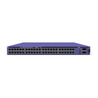
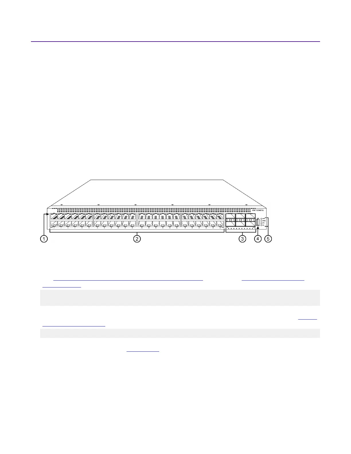
Figure 1: VSP 7200 Series — Front view
1. LEDs indicating port activity are above the RJ-45 and SFP+ port. The up arrow on the left indicates the
top port; the down arrow on the right indicates the bottom port. For a description of what the LEDs mean,
see 100 Mbps/1 Gbps/10 Gbps RJ-45 port LED state indicators on page 38 or SFP and SFP+ port LED
state indicators on page 38.
2. 48 ports — The VSP 7254XSQ has 48 SFP/SFP+ fiber ports. The VSP 7254XTQ has 48 RJ-45 copper
ports.
3. Six QSFP+ ports — The LEDs are below each port. There are four LEDs per port to support
channelization. The up arrows refer to the port above. For a description of what the LEDs mean, see QSFP+
port LED state indicators on page 39.
4. USB port
5. LEDs for system power (PWR), switch status (Status), redundant power supply (RPS), and fan modules
(Fan). For more information, see Switch LEDs on page 37.
The following figure shows the rear of the chassis with three fan modules and one power supply
installed. The fan modules are numbered 1–3 from left to right, and the power supplies are
numbered PSU 1 on the left and PSU 2 on the right.
Installation fundamentals
March 2020 Installing the VSP 7200 Series 19
 Loading...