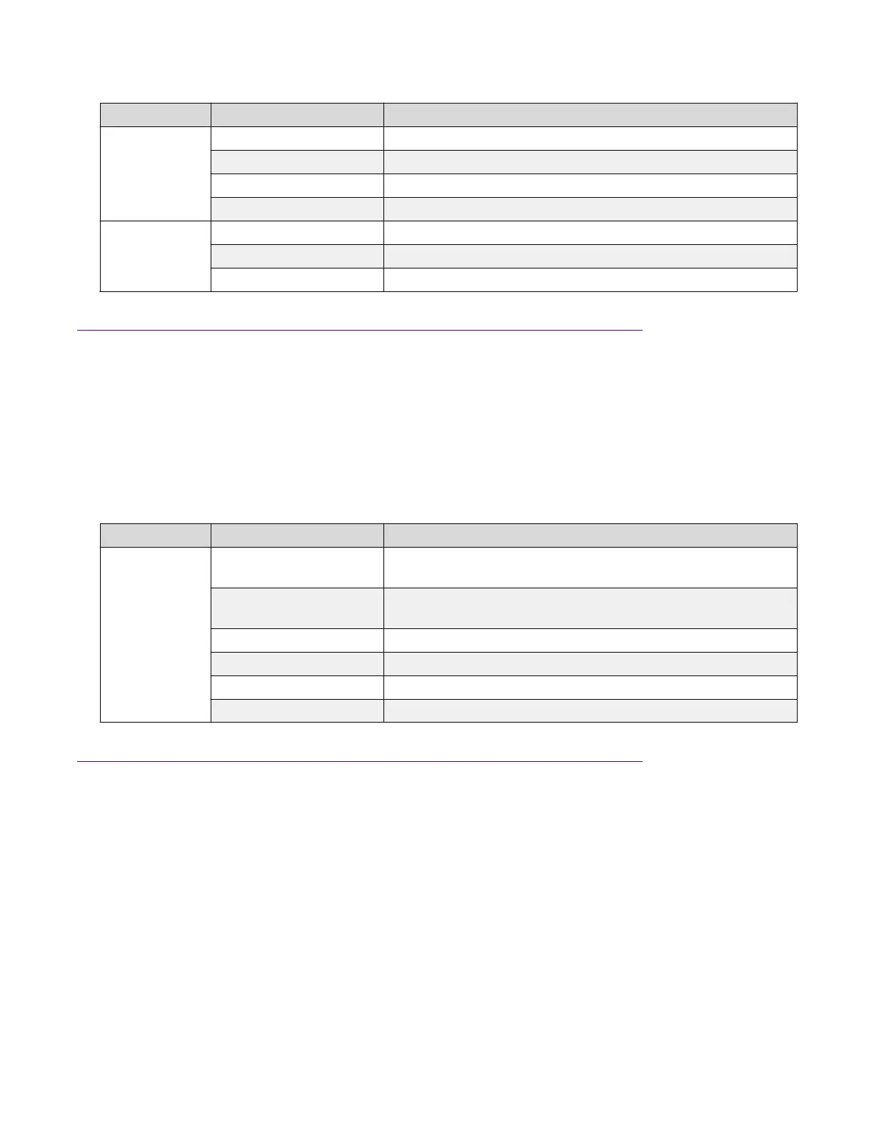
Label Color and Status Description
Amber (blinking) The port received a remote fault indicator (RFI).
Green (steady) The port has established a link.
Green (blinking) The port has established a link and there is data activity.
Green (slow blinking) The port is administratively disabled.
In Use Off Operating at low speed (10 Mbps if SFP, 100 Mbps if SFP+)
Green (steady) Operating at mid speed (100 Mbps if SFP, 1 Gbps if SFP+)
Green (blinking) Operating at high speed (1 Gbps if SFP, 10 Gbps if SFP+)
QSFP+ port LED state indicators
This section describes the transceiver port LED state indicators by color and fluctuation cues. The
Link/Act) indicates whether or not the link is established and if a transceiver is present and active.
Each 40 Gb QSFP+ port can be channelized into 4 x 10 Gb ports. To support channelization, each
QSFP+ port has four status LEDs under the port. When the QSFP+ port is not channelized, only the
LED on the left side of the port is used.
Table 18: SFP/SFP+ port LED state indicators
Label Color and Status Description
Link/Act Off There is no transceiver present and the port is administratively
enabled.
Amber (steady) The port is actively transmitting, but there is no link. This
indicates a local fault.
Amber (blinking) The port received a remote fault indicator (RFI).
Green (steady) The port has established a link.
Green (blinking) The port has established a link and there is data activity.
Green (slow blinking) The port is administratively disabled.
Management port LED state indicators
The management port is on the rear of the chassis between the fans and the right-hand power
supply (PSU2). The management port is the RJ–45 jack above the console port.
The management port provides 10/100/1000 BaseT Ethernet connectivity and uses two bi-colored
LEDs to indicate the activity and speed of the link.
• The LED on the top of the port (Speed) indicates the current speed of the port.
• The LED on the bottom of the port (Link/Act) indicates the status of the link and whether or not
it’s active.
LED state definitions
March 2020 Installing the VSP 7200 Series 39
 Loading...