8. Push excess cable into the lectern.
9. Ensure the locking arms are flush with top and bottom of the touchpanel and fit the
touchpanel into the hole.
z The TLP Pro 720M has four locking arms, two at the top and two at the bottom.
z The TLP Pro 1020M has five locking arms, two at the top and three at the bottom.
10. Secure the touchpanel to the lectern with four #4 screws (not provided), using the pilot holes
drilled in step 5.
11. Replace the bezel by pressing the catches on the bezel into the corresponding holes on the
front of the panel.
Mounting the TLP Pro 720T and TLP Pro 1020T
Desktop Mounting
Placement without a Mounting Kit
Both the TLP Pro 720T and TLP Pro 1020T have stands that allow them to be placed on a
desktop.
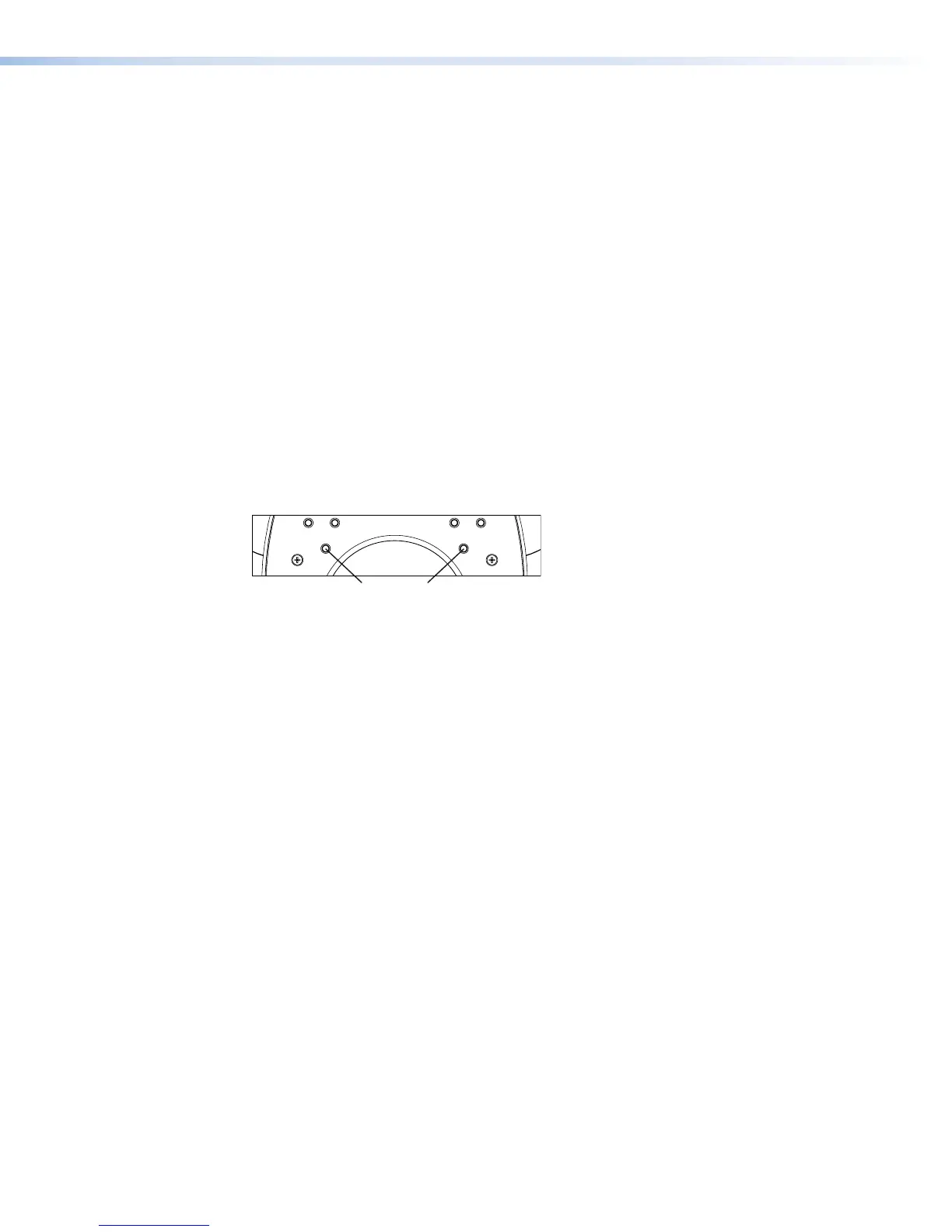
Both units can be secured to the desktop using screws. Figure 22 shows the base of the
TLPPro720T, but the base of the TLP Pro 1020T is similar.
Figure 22. TLP Pro 720T Base (Bottom View), Showing Mounting Holes
1. Mark the location of two holes, 3.07inches (78 mm) apart. This measurement is the same
for both the TLP Pro 720T and the TLPPro1020T.
2. Drill two holes through the desktop from underneath.
3. Attach the touchpanel, using two #8 wood screws through the desktop from underneath
into the two holes in the base.
TLP Pro 720 Series and TLP Pro 1020 Series • Mounting 26