PRODUCT GUIDE: EYEDRO ELECTRICITY MONITORING PRODUCTS
©2011-2023 Eyedro Green Solutions Inc. Page | 9
INSTALL CURRENT SENSORS
MATERIALS YOU WILL NEED
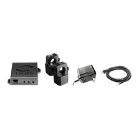
• Eyedro Current Sensors
• Approved bushing or connector (not included)
• Labels (optional – not included)
TOOLS YOU WILL NEED
• Flashlight • Screwdriver • Pliers
PROCEDURE
Current sensors are installed on the individual line (/live/hot) conductors only. This must be done
inside the electrical panel or junction box where the electrical connection is separated into the individual
line, neutral and ground conductors.
Do not install sensors on neutral or ground conductors.
Do not install sensors on extension cords, appliance cords or sheathed cables.
Do not install sensors on conductors exceeding the max rating of the sensor.
1. Turn off the power by disengaging the main disconnect switch or turning off the main breaker.
CAUTION: EVEN WITH THE MAIN BREAKER IN THE 'OFF' POSITION, THE SERVICE
ENTRANCE WIRES WILL STILL BE ELECTRIFIED (BEFORE THE BREAKER). EXTREME
CAUTION SHOULD ALWAYS BE TAKEN WHILE WORKING AROUND ELECTRICITY.
2. Carefully remove the electrical panel cover(s) to expose the conductors.
3. Carefully remove a 'knockout' on the side of the panel and add an approved bushing or connector
to protect the low voltage signal wires that will pass through it.
4. Install one current sensor over each line conductor. Use the figures indicated in
common circuit
types as guidance.
If installing over a single conductor of a parallel feed, ensure the ampacity of a single
conductor (i.e., total ampacity / feeders) does not exceed the rating of the sensor.
5. Optionally, use tape or other label to uniquely identify each sensor at the end of the wire nearest
the connector (i.e., "Sensor 1", "Phase A", etc.).
6. Route sensor cables through the bushing/connector so the plug ends are on the exterior of the
panel.
7. If provided (sold separately), install panel mount power supply or step-down transformer prior to
replacing the panel cover(s) and route the low voltage side through the bushing/connector so the
plug is on the exterior of the panel.
IMPORTANT: Electricity monitoring devices must be powered by a circuit or
receptacle that is downstream of the panel where the current sensors are installed
8. Replace panel cover(s).
9. Turn on the power.