Page 46 of 72
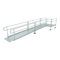
FIG. 5.8
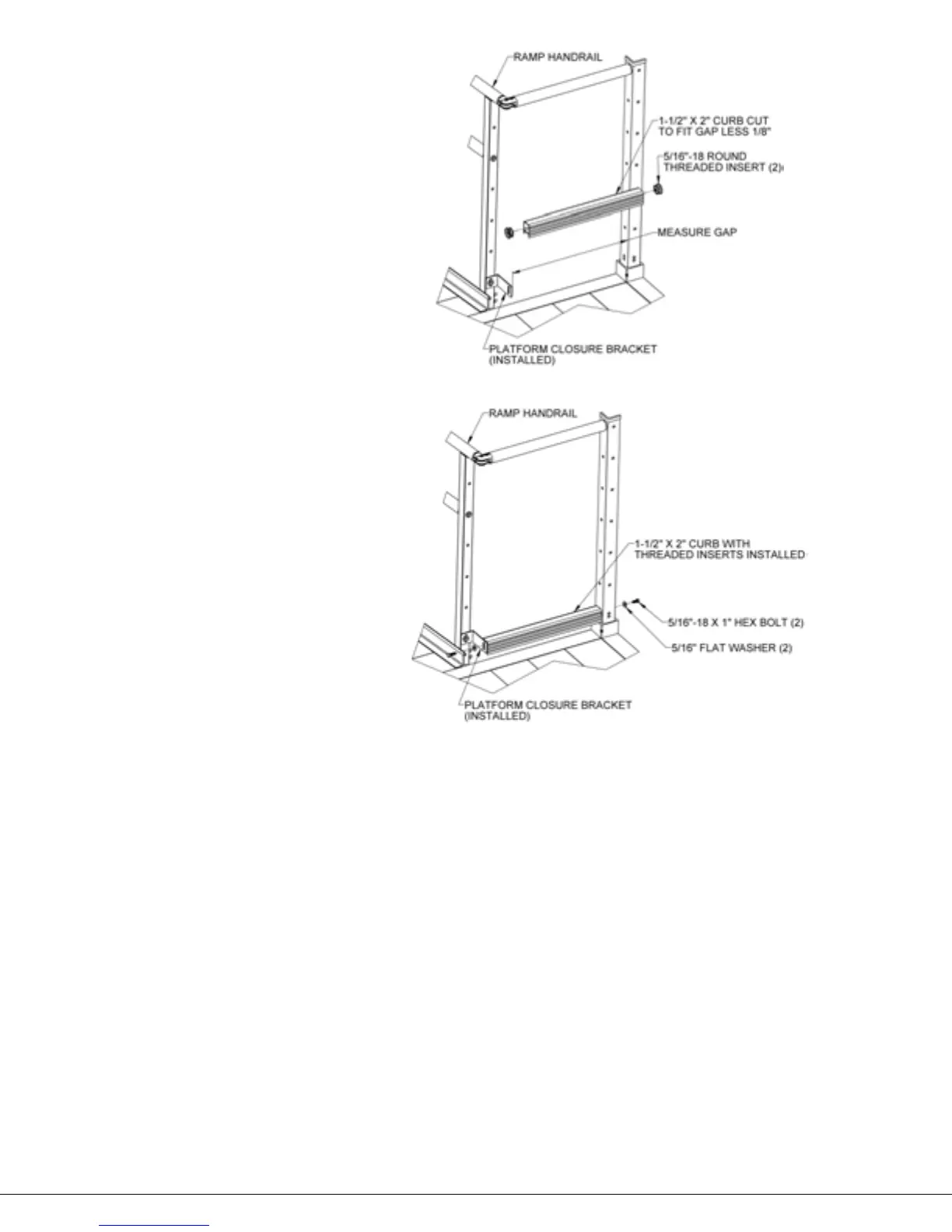
FIG. 5.9
5.4.10. Measure the gap between the long leg of the bracket and the post then cut the 1-1/2” x
2” curb to the measured length, less 1/8” to account for the threaded inserts which will
be installed after cutting (FIG. 5.8).
5.4.11. Insert 5/16”-18 round threaded inserts into both ends of the curb. Use a rubber mallet or
similar tool to fully seat the threaded inserts as needed (FIG. 5.8).
5.4.12. Install 5/16″-18 x 1″ hex bolts through a 5/16” flat washers, the long leg of the closure
bracket, and the platform post into the 5/16”-18 round threaded inserts installed in the
curb. Use the hole which is 1/2” above the lowermost hole in the platform post to align
the curb correctly. (FIG. 5.9).
5.4.13. Confirm all fasteners are tightened securely. If you are installing a Single Line closure, the
installation is complete.