14
ENGLISH
ENGLISH
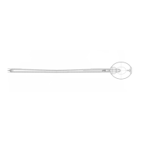
• curved arms (Fig. 13)
Place the telescopic arm in position as shown in figure 13.
Cut the outer profile of the telescopic arm at point A.
Cut the inner profile at point B.
Ü Leave a gap of about 1 cm at the ends of both profiles.
A
B
Fig. 13
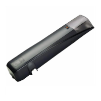
TABLE 4 550 MP CONTROL BOARD COMPONENTS
F1 Fuse F1 5x20 5A/250V (mains circuit)
F2 Fuse F2 5x20 500mA/250V (accessories)
TF1 Transformer
LP1 Courtesy lamp 25W 220V E14
DL Display
J1 230VAC power supply input terminal board
J2 Motor output terminal board, flashing lamp and outside courtesy lamp
J3 Low voltage input/accessories terminal board
J4 Rapid connector for decoding cards/RP receivers
P1
"+"
programming key
P2
"-"
programming key
P3
"F"
programming key
5. START-UP
5.1. CONTROL BOARD CONNECTION
ÜBefore attempting any work on the control board(connections,
programming, maintenance), always turn off power.
Important: High voltage could be present when disconnecting
the J2 terminal board.
Observe points 10, 11, 12, 13 and 14 of the GENERAL SAFETY
OBLIGATIONS.
Observing the indications in Fig.3, install the raceways and make
the electric connections from the 550 MPD control board to the
selected accessories.
Always separate power cables from control and safety cables
(push-button, receiver, photocells, etc.). To prevent any electric
noise whatever, use separate sheaths.
5.1.1. 550 MPD CONTROL BOARD
The 550MPD control board (supplied with the 550 I package) is
able to command both operators in case of double application.
Instead of the control board, the 550 Slave has an interface
electronic card on which the courtesy lamp is fitted.
5.1.2. LAY OUT OF 550 MPD CONTROL BOARD
TABLE 3 HARDWARE CHARACTERISTICS 550MPD
Power supply 230VAC - 50Hz
Max. absorbed power 12VA
Motors max. load 800W
Power supply for accessories 24Vdc
Accessories max. load 300mA
Operating ambient temperature - 20°C + 55°C
Protection fuses mains circuit / accessories
Rapid connector - for decoding cards or RP receivers -
Terminal boards pull-out
Open / Stop / Closing safety devices
Terminal board inputs Opening safety devices /
Opening limit-switch / Closing limit-switch
flashing lamp 230VAC - 60W
Terminal board outputs motor
outside courtesy lamp 230 VAC
24 Vdc accessories power supply
Max. load of built-in courtesy lamp 25W
Max. load of outside courtesy lamp 250W
TABLE 2 550 MPD OPERATING PARAMETERS
Logic automatic/semi-automatic
Pause time programmable from 0 to 4 min. (default 2 min.)
Operating time programmable from 0 to 59 sec. (default 20 sec.)
Max torque at thrust Yes/No
Fail safe Yes/No
Pre-flashing programmable from 0 to 10 sec. (default 0 sec.)
Electronic clutch programmable on 8 levels
Limit-switch tripping modes 4 types of operation
Courtesy timer programmable from 0 to 4 min. (default 30 sec.)
Safety devices tripping modes 3 types of operation
9) Fit the inner profile of the telescopic arm to the transmission
shaft and weld securely.
4.5. ADJUSTING THE COUNTERWEIGHTS
On completing mechanical installation, check whether the door
has become unbalanced by the weight of the operator and
accessories.
If necessary, change the counterweights.
For optimum balancing, the door should remain in equilibrium in
an intermediate position (45°) with the operator released.
Also check that the door opens and closes smoothly without jerky
or irregular movements.
12345678910
11 12
13
14
15
16
PE
NL
J3
J5
J4
J2
J1
+
-
F
FCA
OPEN
FCC
FSWOP
STOP
FSWCL
F2
F1
TF1
F1
J4
LP1
J3
TF1
DL
P1
P2
P3
J1 J2
F2
Fig. 14