37
38
39
40
B614 35 732998 - Rev.A
J10
J13
BUS
BUS
GND
LAMP
OUT 4
OUT 3
OUT 2
OUT 1
+24V
LAMP
PE
N
L
N
L
6 A
OPEN
1
2
3
4
5
6
+24V
GND
EMER
STOP
CLOSE
LOOP 2
LOOP 2
LOOP 1
LOOP 1
XF 433-868
AC MAIN
ENC
TRAFFIC
LAMP
LIGHT
BEAM
COM
BLR
BLG
MOT
MOT
M
J20
J3
GND
OUT 4
OUT 3
OUT 2
OUT 1
+24V
LAMP
PE
N
L
N
L
6 A
OPEN
1
2
3
4
5
6
+24V
GND
EMER
STOP
CLOSE
LOOP 2
LOOP 2
LOOP 1
LOOP 1
XF 433-868
AC MAIN
ENC
TRAFFIC
LAMP
LIGHT
BEAM
COM
BLR
BLG
MOT
MOT
M
BUS
BUS
GND
LAMP
OUT 4
OUT 3
OUT 2
OUT 1
+24V
LAMP
PE
N
L
N
L
6 A
OPEN
1
2
3
4
5
6
+24V
GND
EMER
STOP
CLOSE
LOOP 2
LOOP 2
LOOP 1
LOOP 1
XF 433-868
AC MAIN
ENC
TRAFFIC
LAMP
LIGHT
BEAM
COM
BLR
BLG
MOT
MOT
M
J23
J11
BUS
BUS
GND
LAMP
OUT 4
OUT 3
OUT 2
OUT 1
+24V
LAMP
PE
N
L
N
L
6 A
OPEN
1
2
3
4
5
6
+24V
GND
EMER
STOP
CLOSE
LOOP 2
LOOP 2
LOOP 1
LOOP 1
XF 433-868
AC MAIN
ENC
TRAFFIC
LAMP
BEAM
COM
BLR
BLG
J18
J21
Translation of the original instructions
ENGLISH
as Fail-Safe. In this way the functioning of the pho-
tocells is checked before each closure: the test consists
in breaking the power supply to the TX momentarily
and checking the change of status of the input. If the
test fails the electronic board does not command the
movement.
EXTERNAL LOOPS
!
The magnetic coil detectors must not be used to
detect pedestrians, cycles and motorbikes. If it is
not possible to prevent them passing, other devices
such as photocells are necessary.
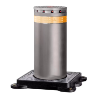
(37) Connect the magnetic coil detectors to termi-
nal boards J10 (LOOP 1) or J13 (LOOP 2).
LOOP 1
Opening coil
NO contact, connect a detector that commands the
opening of the barrier when a contact is closed
LOOP 2
Transit coil
NO contact, connect a detector that commands
the closure at the disengagement when a contact
is closed
The engagement of the loop during the closure
inverts the movement; the barrier cannot close as
long as the loop is engaged
BUS DEVICES
Li
If no BUS 2easy devices are used, leave the BUS 2easy
terminal board free.
See § 9.4 for the connection and orientation.
OUT OUTPUTS
Li
Respect the 100mA max load for each output.
Open Collector Outputs: the activation of the output
and its polarity can be configured by Advanced pro-
gramming.
OUT active OUT not active
NO polarity 0 V
"
open circuit
NC polarity open circuit 0 V
"
(38) Connect the devices required to terminal
board J20.
24 V
"
FLASHING LIGHT
See § 9.1 for the connection.
MOTOR
(39) The motor wire is connected in the factory
for a RH barrier.
Invert the wires if a LH barrier is being installed.
ENCODER
The encoder wire is connected in the factory.
red
blue