20
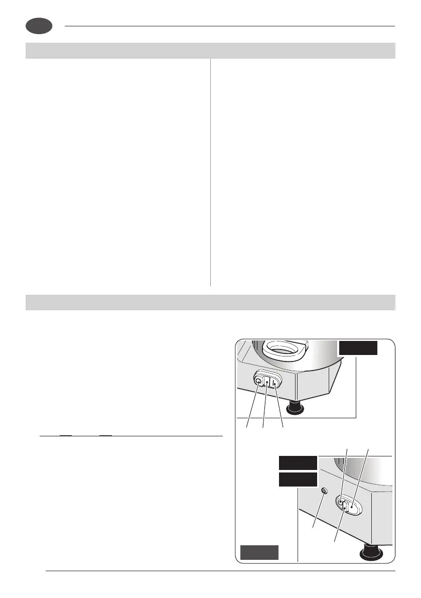
14 15 13
15
17
18
16
Fig. 6
“C5”
“C8”
“C3”
EN
4
.1 - Installation
Placethesliceronawellleveled,smooth,
dryandstableplane,suitabletosupport
itsweight.
4
.2 -
Electric connection
Installtheslicerintheimmediatevicinity
ofanoutlettoCEstandardsderivedfrom
a system that complies with applicable
regulations.
It is the user’s responsibility to verify
the suitability and proper functioning of
theelectricalsystem (supplyline,outlet,
distribution panel,differential thermal
magneticcircuitbreakerprotection,system
grounding).
Before executing the connection
check that the characterisitcs of the
power supply network correspond to
thoseindicatedonthenameplateofthe
slicer.
INSTALLATION AND PRELIMINARY CHECKS
USING THE MACHINE
5
.1 -
Start and stop button
• Starttheappliancebypressingtherelevant
button:
-model“C3”:“I”button(13);
-models“C5”-“C8”:“START”button(16).
Theindicatorlight(15)switcheson.
• For“C5”and“C8”withspeedchangeronly:
theindicatorlight(15)switchesonafterthe
plughasbeenconnectedtothesocket.