N
EW
F
EATURES
Page i of ii
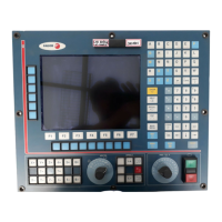
CNC 8055 / CNC 8055i
I
NDEX
Version 7.01
1 Detected errors ..................................................................................................................1
2 Sampling period .................................................................................................................2
3 The meaningless zeros will not be displayed .....................................................................2
4 Management of the new Sercos board ..............................................................................3
5 Key inhibiting codes for the monitors .................................................................................3
6 New work languages ..........................................................................................................3
7 Load version without using an external microprocessor. ...................................................3
8 WINDNC improvements .....................................................................................................4
9 Telediagnosis .....................................................................................................................4
10 Improvements to the profile editor ......................................................................................6
11 Modified variables ..............................................................................................................6
12 New variables .....................................................................................................................7
13 New range of OEM subroutines. ........................................................................................9
14 RPT instruction with program number definition ................................................................9
15 Improved non-random tool magazine management ..........................................................9
16 Improved drive parameter management ..........................................................................10
17 User and OEM arithmetic parameters ..............................................................................10
18 Exponential type of leadscrew backlash peak .................................................................10
19 Functions associated to machine safety ..........................................................................11
19.1 Limit the feedrate of the axes and the spindle speed ................................................11
19.2 Cycle Start disabled by hardware errors ...................................................................12
19.3 Maximum spindle machining speed. .........................................................................12
20 Axes (2) controlled by a drive ...........................................................................................13
21 Mandatory home search ..................................................................................................13
22 Change of active tool from the PLC .................................................................................14
23 Synchronize a PLC axis with a CNC axis ........................................................................14
24 Error register ....................................................................................................................15
25 Path JOG mode ...............................................................................................................15
26 Tool inspection .................................................................................................................17
27 New instructions in the configuration language ................................................................17
28 Improvements in tool compensation ................................................................................18
29 Improvements in high speed machining ...........................................................................19
30 New graphics option .........................................................................................................20
31 Improvement in the tool measuring cycle PROBE1 .........................................................20
31.1 Measure or calibrate the tool length. .........................................................................21
31.2 Measure or calibrate the radius of a tool. ..................................................................23
31.3 Measure or calibrate the tool radius and length. .......................................................24
32 Oscilloscope function .......................................................................................................26
32.1 Configuration .............................................................................................................27
32.2 Scale / Offsets ...........................................................................................................32
32.3 Analysis .....................................................................................................................33
32.4 Parameters ................................................................................................................33
32.5 Actions .......................................................................................................................34
32.6 Begin .........................................................................................................................34
33 MC model. Execute a part-program .................................................................................35
34 MC model. Maintain F, S y Smax on power up ................................................................35
35 MC model. Messages and warnings ................................................................................35
36 MC model. Tool calibration ..............................................................................................35
37 MC model. Cycle selection ...............................................................................................36
38 MC model. Auxiliary M functions in all the cycles ............................................................37
39 MC model. Modifications in the tapping cycle ..................................................................38
40 MC model. Modifications in the Multiple milling and positioning cycles ...........................38
41 MC model. Icon indicating the available options ..............................................................38
42 MC model. Tool measurement and calibration ................................................................39

 Loading...