Hardware configuration
CNC 8065
2.
(REF: 1404)
·27·
HARDWARE STRUCTURE.
2.1 Possible configurations.
The following description only refers to the central unit, keyboard and operator panel. The
configuration of the rest of the elements, like the battery, is described in their own chapters.
[ICU + LCD10K]
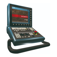
The central unit is located on the rear of the monitor. The keyboard and the operator panel
are integrated into the monitor.
Basic connection.
• The keyboard, the operator panel and the remote modules are connected through the
CAN bus.
• The Sercos bus is used to communicate with digital Fagor drives. It is also possible to
communicate with analog drives.
Remember that the ground terminals of all the elements making up the system must be
connected to a single ground point.
GND
L
SH
SH
H
X3
GND
L
SH
SH
H
X2
CAN
POWER 24I/16O
ERR
RUN
X4
X5
X6
X7
I13
I24
I1
I12
GND
O16
O9
+24V
GND
O8
O1
+24V
X1
CHS
GN D
+24V
4
0
1
F
E
D
C
B
A
9
8
7
6
5
3
2
ADDRESS
SPEED
1
0
LT
1
0
DIGITAL IN/OUT
X5
X6
X7
X8
I13
I24
I1
I12
GND
O16
O9
+24V
GND
O8
O1
+24V
X1
X2
X3
X4
I13
I24
I1
I12
GND
O16
O9
+24V
GND
O8
O1
+24V
GND
L
SH
SH
H
X3
GND
L
SH
SH
H
X2
CAN
POWER 24I/16O
ERR
RUN
X4
X5
X6
X7
I13
I24
I1
I12
GND
O16
O9
+24V
GND
O8
O1
+24V
X1
CHS
GN D
+24V
4
0
1
F
E
D
C
B
A
9
8
7
6
5
3
2
ADDRESS
SPEED
1
0
LT
1
0
DIGITAL IN/OUT
X5
X6
X7
X8
I13
I24
I1
I12
GND
O16
O9
+24V
GND
O8
O1
+24V
X1
X2
X3
X4
I13
I24
I1
I12
GN D
O16
O9
+24V
GN D
O8
O1
+24V
CAN CAN
CAN
SERCOS
DRI VE MOD ULE
DRI VE MOD ULE
DRI VE MOD ULE

 Loading...